Lifting Products Product Warnings / Cautions
BLOCKS / SHEAVES WARNINGS:

Crosby Tackle Block & Sheave Assembly Warnings
- A potential hazard exists when lifting or dragging heavy loads with tackle block assemblies.
- Failure to design and use tackle block systems properly may cause a load to slip or fall – the result could be serious injury or death.
- Failure to design lifting system with appropriate sheave assembly material for the intended application may cause premature sheave, bearing or wire rope wear and ultimate failure – the result could be serious injury or death.
- A tackle block system should be rigged by a qualified person as defined by ANSI / ASME B.30.
- Instruct workers to keep hands and body away from block sheaves and swivels – and away from “pinch points” where rope touches block parts or loads.
- Do not side load tackle blocks.
- See OSHA Rule 1926.1431(g) and 1926.1501(g) for personnel hoisting by cranes and derricks, and OSHA Directive CPL 2-1.36 – Interim Inspection Procedures During Communication Tower Construction Activities. Only a Crosby or McKissick® Hook with a PL latch attached and secured with a bolt, nut and cotter pin (or toggle pin) or a PL-N latch attached and secured with toggle pin; or a Crosby hook with an S-4320 latch attached and secured with cotter pin or bolt, nut and pin; or a Crosby SHUR-LOC® Hook in the locked position may be used for any personnel hoisting. A hook with a Crosby SS-4055 latch attached shall NOT be used for personnel lifting.
- Instruct workers to be alert and to wear proper safety gear in areas where loads are moved or supported with tackle block systems.
- Use only genuine Crosby parts as replacement.
- Read, understand, and follow these instructions to select, use and maintain tackle block systems.
For complete warning and application information, see The Crosby Group at www.thecrosbygroup.com.
General Cautions or Warnings
Ratings shown in Crosby Group literature are applicable only to new or “in as new” products. Working Load Limit ratings indicate the greatest force or load a product can carry under usual environmental conditions. Shock loading and extraordinary conditions must be taken into account when selecting products for use in tackle block systems. Working Load Limit ratings are based on all sheaves of tackle block system being utilized. If all sheaves are not utilized, balance must be maintained, and the Working Load Limit must be reduced proportionally to prevent overloading sheave components. Changes from full sheave reeving arrangement should be only at the recommendation of a qualified person, and incorporate good rigging practices.
In general, the products displayed in Crosby Group literature are used as parts of a system being employed to accomplish a task. Therefore, we can only recommend within the Working Load Limits, or other stated limitations, the use of products for this purpose.
The Working Load Limit or Design (Safety) Factor of each Crosby product may be affected by wear, misuse, overloading, corrosion, deformation, intentional alteration, and other use conditions. Regular inspection must be conducted to determine whether use can be continued at the catalog assigned WLL, a reduced WLL, a reduced Design (Safety) Factor, or withdrawn from service.
Crosby Group products generally are intended for tension or pull. Side loading must be avoided, as it exerts additional force or loading which the product is not designed to accommodate. Always make sure the hook supports the load. The latch must never support the load.
Welding of load supporting parts or products can be hazardous. Knowledge of materials, heat treatment, and welding procedures are necessary for proper welding. Crosby Group should be consulted for information.
Crane component parts, i.e. the boom, block, overhaul ball, swivel, and wire ropes are metallic and will conduct electricity. Read and understand OSHA standard covering crane and derrick operations (29 CFR 1926.550 SUBPART N) before operating proximate to power lines.
Miller Block Warnings & Precautions
All ratings shown in any Miller literature are based on the products being in a new and unused condition. When selecting a product, consideration must be given to the greatest load the product will see, therefore, shock loading must be considered in the overall system design.
All products manufactured by Miller Products are sold with the express understanding that the customer is thoroughly familiar with the safe and proper use and application of the product.
In selecting a Miller product, such factors as extreme heat or cold, excess humidity, moisture, contaminated air, etc. must be considered since these may adversely affect longevity, performance and Working Load Limit.
Do not immerse any standard Miller product in water. Contact the factory for assistance in selecting the special product designed to meet fresh and saltwater applications.
Lift only those loads for which the Miller product is designed. Federal crane regulations prohibit the transport of personnel on any load or wire rope attachment (OSHA 1910, 180-h-3-v).
Miller products are generally designed for applications of tension or straight pull. Side loading must be avoided since it exerts additional force which the product is not designed to accommodate.
HOOK LATCHES—
All Miller products that utilize hooks are equipped at the factory with hook latches. The only function of a hook latch is to retain loose slings or devices under slack conditions, i.e. no load. They are not intended to be anti-fouling devices, so caution should be used to prevent the latch from supporting any of the load. Routine inspection of the latches must be made to ensure their proper operating conditions. Hook applications might require other hook latches. Should you have any questions regarding hook latches, contact the factory.
WHENEVER WEDGE SOCKETS ARE UTILIZED THESE TWO PRECAUTIONS MUST BE TAKEN:
- When installing wire rope always pre-load the wedge with the wire rope in place. Then attach the end of the rope to the main line with the first clip to be located directly above the socket. It is imperative that the clips and clamps be installed precisely as specified by the manufacturers and in the number and sizes approved by the fitting manufacturers.
- Make allowance for the crimping effect common with all types of wedge sockets. Experience shows the Maximum Load Limit on a line will be reduced by 20% or more with this type of fitting.
NEVER WELD ON ANY MILLER PRODUCT.
Should any modification or repairs be required on any Miller product, contact the factory for information.
INSPECT AND MAINTAIN REGULARLY.
All Miller products are mechanical components and are subject to wear. Worn components do not have the same Working Load Limit as do new components. The total responsibility for the inspection, maintenance and continued use is entirely up to the purchaser/user. Remember, visual inspection may not be sufficient and examination methods such as X-ray, ultrasonic testing, magnetic particle inspection, dielectric resistance and others, might be required to establish the present integrity of the product.
Check to see that your equipment is being inspected and tested in accordance with all applicable governmental rules and regulations. Should any Miller products become worn and in need of repair, the responsibility for the actual repair work will be borne solely by the party making such repairs. It is recommended that the factory be contacted should there be any questions whatsoever relating to a repair. See Maintenance and Inspection.
INSULATING LINKS
ELECTRICAL PERFORMANCE OF INSULATING LINKS DEGRADES WHEN LINKS ARE NOT KEPT FREE OF SURFACE DIRT AND CONTAMINATION. INSULATING LINK VOLTAGE RATINGS ASSUME CLEAN AND DRY LINKS AND A DRY ENVIRONMENT. In the case of ELECTRICAL POWER LINE SAFETY use of an insulating link alone in the absence of other required measures is NOT ACCEPTABLE. OSHA power line safety requirements involving the use of cranes and derricks can be found in US federal regulation 29 CFR Part 1926, latest edition.
REMEMBER: External factors will affect the longevity of the product. There is no defined period for the useful life of any Miller product. It is the user’s responsibility to maintain and check the product. Even after a short period of use circumstances may require the product to be withdrawn from service. Should any questions arise during the inspection of any Miller product that relate to its intended application or need for repair, promptly remove the product from service.
PROOF LOAD
The recommended proof load on all items in this catalog is 2 times the Working Load Limit unless otherwise indicated.
SPARE PARTS
Use only new genuine Miller parts for replacement or repair.
PRODUCT LABELS
Per ANSI 535.4-1991 labels should be inspected and cleaned and safety related labels replaced when no longer legible. Contact Miller for replacements.
DIMENSIONS
Dimensions in this catalog are generally nominal dimensions in inches unless otherwise indicated. Where tolerance information is needed but is not indicated please contact Miller for applicable tolerances.
WEIGHTS
Weights in this catalog are generally in pounds unless otherwise indicated.
For complete warning and application information, see Miller Lifting Products at www.millerproducts.net.
Gunnebo Johnson Crane Block Warnings
- Never use a crane block without training.
- Always inform yourself…Ask your employer for the manufacturer’s crane block use limitations.
- Always comply with applicable Country regulations.
- Always know load weight.
- Never use a crane block without a legible rated load tag.
- Never overload a crane block.
- Never ride on a crane block or load.
- Never use an improperly rigged crane block.
- Never use a worn-out or damaged crane block.
- Never use a crane block in extreme temperatures.
- Never use a crane block in acidic conditions.
For complete warning and application information, see Gunnebo Johnson at www.gunnebojohnson.com.
Jeamar Blocks Warnings
WARNINGS:
- Ensure the correct equipment is obtained and installed for the application.
- Ratings shown in Jeamar literature are applicable only to new products.
- Working load limits shown are the maximum load the product is authorized to support under normal environmental conditions. Shock loading and abnormal conditions must be taken into account when selecting products.
- Working load limits shown are the maximum load the product is authorized to support under normal environmental conditions. Regular inspections must be conducted to ensure the equipment continues to meet the most current revision of the published standard.
AVOID SHOCK LOADS
- These are transient loads that exceed the steady-state load. Shock loads are caused by sudden accelerations, usually due to unrestrained loads, swing loads, jerking, or impacting of the load. The working load limit may well be exceeded under these conditions.
- Welding to any Jeamar products can be hazardous and should only be implemented after written permission from Jeamar. Jeamar products are sold on the strict understanding that all product selection is the full responsibility of the purchaser. Jeamar accepts no liability for the use, misuse or incorrect application of its products.
For complete warning and application information, see Jeamar, Inc. at www.jeamar.com.
Rope BlockBlock Warnings
Where equipment has swivelling and moving parts there are potential safety hazards. Care should be taken when working with or repairing such equipment. If used incorrectly breakage could occur inflicting injury or death. When equipment is in use do not put hands: between sheaves, side plates and guards. In area of becket, hook, hook nut and cross head.
Take great care to avoid clothing becoming trapped. Repair and reeving should be carried out by trained personnel only. Power should be switched off before operations are carried out. Work should only take place when equipment is seated on a firm surface.
Limitation of Use
- Working load limit (WLL) should never be exceeded.
- Hook-blocks should be used in vertical lift only.
- Rigging blocks should be used only as in design specifications. Blocks should not be used for towing unless specifically designed and marked for that purpose.
- Swivels should be used in either vertical or horizontal plain only.
- Horizontal and vertical lead sheaves used only as indicated in description.
- Shock or side loading should not be applied unless equipment is designed for that purpose.
- Load should always be in seat of hook or eye. Never at point!
For complete warning and application information, see Ropeblock BV at www.ropeblock.com.
LIFTING CLAMPS WARNINGS:
J.C. Renfroe Definitions / Warnings:
VERTICAL LIFT:
The lifting of a single plate or member in which the lifting force exerted by the rigging is directly above and in line with the lifting shackle.
VERTICAL TURN/LIFT:
A vertical turn/lift clamp is a vertical lifting clamp specifically intended to turn a single plate or member thru a ninety degree (90°) arc and back to vertical thru the same ninety degree (90°) arc or from horizontal to vertical to horizontal thru a one hundred and eighty degree (180°) arc.
During the turning operation the edge of the plate opposite the edge to which the clamp is attached should always be in contact with a supporting surface such as a factory floor and the load on the clamp should not exceed one half rated capacity of clamp.
HORIZONTAL LIFT:
Clamps (used in pairs or multiples) are attached to the side edges of a plate or bundle of plates positioned horizontally to the floor level. The rigging attached to clamps is generally multi-legged slings with the connecting point of the slings being approximately centered between the distance separating the clamps.
WARNING:
The capacity of all horizontal clamps is based on a sling angle of sixty degrees (60°). Sling angles less than sixty degrees (60°) increase the load exerted on the clamps. Sling Angles greater than 60° reduce gripping force, Do not exceed 60°.
STEEL PLATES:
Unless otherwise specified, lifting clamps are manufactured to handle hot-rolled steel plates whose Brinell Hardness does not exceed 300.
WARNING:
Do not lift plates with coatings or mill scale that prevent the gripping surfaces of the clamp from making positive contact with the base metal. For applications not covered by the above information, secure written recommendations from RENFROE.
FINISHED AND POLISHED PLATES:
Steel plates in this category having other than hot-rolled surfaces such as stainless steel, etc., are generally handled using non-marring clamps incorporating smooth gripping surfaces.
WARNING:
For applications using clamps with serrated gripping surfaces on finished or polished plates, secure written recommendations from RENFROE.
STRUCTURAL MEMBERS—FABRICATED SECTIONS:
Unless otherwise specified, clamps described as capable of handling structural members and fabricated sections are limited to hot-rolled steel whose Brinell Hardness does not exceed 300.
WARNING:
For applications not covered by the above information, secure written recommendations from RENFROE.
RATED CAPACITY:
ALL RENFROE CLAMPS ARE RATED INDIVIDUALLY. The rated capacity of a RENFROE product is based on the product being in ‘new or as new’ condition and represents the maximum load the product is to be subjected to when utilized in the manner described in this manual. Wear, misuse, abuse and other factors relating to usage may reduce the rated capacity. A 20% UNDERLOADING CAN BE ALLOWED WHEN THE CONDITIONS AND WARNINGS ARE MET IN THIS MANUAL. UNDER LOADING OCCURS WHEN LESS THAN 50% OF LOAD RATING OF A CLAMP IS LIFTED. Shock loading and the factors listed must be taken into consideration when selecting a RENFROE product for a given application.
PLATE THICKNESS:
The minimum and maximum plate thickness a clamp specified for handling plates is capable of lifting.
WARNING:
Never use a clamp for lifting a plate where the plate thickness is less than or greater than the minimum and maximum stenciled on the clamp.
JAW OPENING:
The minimum and maximum thickness of a member of a clamp specified as having a JAW OPENING is capable of handling.
WARNING:
Never use a clamp on a member whose thickness is less than or greater than the range of jaw opening stenciled on the clamp.
OPERATING TEMPERATURES:
Unless specified under the Applications Section of the individual model, the approved operating temperature of RENFROE clamps is from zero degrees Fahrenheit (-18 Celsius) to a maximum of 200 degrees Fahrenheit (+93 degrees Celsius). The minimum and maximum temperatures apply to both ambient and the material being handled by the clamp.
WARNING:
Secure written authorization from RENFROE before using clamps in temperatures other than shown.
‘HOT LIFTS’:
The Model R and S clamps are available in modifications that are capable of making lifts where the temperatures of the member being lifted exceeds 200 degrees Fahrenheit (+93 degrees Celsius). Depending on conditions a lift may exceed 1000 degrees Fahrenheit (538 degrees Celsius). The exact application and temperatures of the plates to be handled are critical in selecting the proper model.
WARNING:
Secure written instructions from RENFROE for all hot lift applications.
LOCKING CLAMPS:
Locking clamps are divided into the categories listed below. With the exception of the ‘Locking Wedge’ and ‘Locking Screw’ type the purpose of the locks are to facilitate the attaching and removing of the clamp from the member being handled.
‘Lock Closed’ – an overcenter spring loaded mechanism in which the spring exerts a force on the gripping cam when the lock handle is moved to the ‘Lock Closed’ position. When the handle is moved to unlocked position the force exerted by the spring is relaxed and the gripping cam may be retracted by pushing the lifting shackle into the body of clamp. Typical ‘Lock Closed’ clamps are Models DG, FR, M and HRS.
‘Lock Open Only’ – normally used on ‘Hot Lift’ clamps and consists of a manually operated ‘Lock Stop Pin’ that is inserted when gripping cam of clamp is retracted and removed when clamp is positioned on the plate. Tag line may be used to permit operator to remove pin from a greater distance from clamp. Typical ‘Lock Open Only’ clamp is the Model RO.
‘Lock Open-Lock Closed’ – an over-center spring loaded mechanism in which the spring exerts a force on the gripping cam when the lock handle is moved to the ‘Lock Closed’ position. When the handle is moved to the ‘Lock Open’ the gripping cam is maintained in the retracted position for ease in installing the clamp on a plate or member. The Model FRD contains individual ‘Lock Open’ and ‘Lock Closed’ mechanisms that must be operated separately. Typical ‘Lock Open-Lock Closed’ clamps are Models FRD, R, S, SD, SEA, SX, TL, TLA and the J-Series.
‘Locking Wedge’ – is a fluted steel wedge that is driven in place with a hammer. The body of the wedge is positioned in a slot in the clamp body with the fluted edges contacting the member to which the clamp is being attached. Typical ‘Locking Wedge’ clamps are Models A1, B1, B2 and PB.
‘Locking Screw’ – ‘Lock Screw’ clamps depend on manually adjusting a screw to hold the gripping surface in place for lifting and removing the clamp from member being lifted. Typical ‘Locking Screw’ clamps are Models AC, ACP, BC, NM, PC, SCP, SCPA and RSC.
NON-LOCKING:
‘Non-Locking’ clamps have no mechanisms to aid in attaching or removing clamp from member being lifted. It is necessary to have position of clamp maintained on the member being lifted until a properly applied force is exerted to the lifting shackle. Typical ‘Non-Locking’ clamps are Models AST, ASTL, BD, HR, HDR, HRS and WHSR.
WARNING:
A pointing out and notice of danger. The purpose of a ‘WARNING’ is to apprise the operator and all other affected persons of the existence of danger of which he should be but may not be aware; and to enable the operator to protect himself and others, where applicable, against such danger. An attempt is made herein to warn against reasonable and reasonably foreseeable danger in the proper use and possible reasonable misuse of RENFROE products.
For complete warning and application information, see J.C. Renfroe & Sons at www.jcrenfroe.com.
Crosby IP / Clamp-Co Lifting Clamp Warnings:
WARNING:
- Loads may disengage from clamp if proper procedures are not followed.
- A falling load may cause serious injury or death.
- The clamp shall not be loaded in excess of its rated load or handle any load for which it is not designed. Read instructions in user manual to determine minimum load permitted and proper load thickness.
- Never operate a damaged or malfunctioning clamp, or a clamp with missing parts.
- Clamp not to be used for personnel hoisting.
- Prohibition of handling above persons.
- Do not leave suspended loads unattended.
- Operator and other personnel shall stay clear of the load.
- Do not lift loads higher than necessary.
- Do not make alterations or modifications to clamp.
- Do not remove or obscure warning labels.
- See ANSI/ASME B30.20 BELOW-THE-HOOK LIFTING DEVICES for additional information.
- Read, understand, and follow these instructions and the product safety information in user manual before using clamp.
For complete warning and application information, see The Crosby Group at www.thecrosbygroup.com.
SAC Plate Clamp Warnings:
- Select proper size clamp for the job.
- Determine the weight of the plate to be lifted.
- Do not exceed WLL (Working Load Limit) shown on clamp.
- Plate thickness must be within grip range shown on clamp.
For complete warning and application information, see Apex Tool Group at www.apexhandtools.com.
GXL Clamp Warnings:
- Select proper size clamp for the job.
- Determine the weight of the plate to be lifted.
- Do not exceed WLL (Working Load Limit) shown on clamp.
- Plate thickness must be within grip range shown on clamp.
For complete warning and application information, see Apex Tool Group at www.apexhandtools.com.
Locking E Clamp Warnings:
- Select proper size clamp for the job.
- Determine the weight of the plate to be lifted.
- Do not exceed WLL (Working Load Limit) shown on clamp.
- Plate thickness must be within grip range shown on clamp.
For complete warning and application information, see Apex Tool Group at www.apexhandtools.com.
GX Clamp Warnings:
- Select proper size clamp for the job.
- Determine the weight of the plate to be lifted.
- Do not exceed WLL (Working Load Limit) shown on clamp.
- Plate thickness must be within grip range shown on clamp.
For complete warning and application information, see Apex Tool Group at www.apexhandtools.com.
HYDRAULICS WARNINGS:
PowerTeam Hydraulics General Warnings
It is the operator’s responsibility to read and understand the following safety statements,
- Only qualified operators should install, operate, adjust, maintain, clean, repair, or transport this machinery.
- These components are designed for general use in normal environments. These components are not specifically designed for lifting and moving people, agri-food machinery, certain types of mobile machinery or special work environments, such as: explosive, flammable or corrosive. Only the user can decide the suitability of this machinery in these conditions or extreme environments. Power Team will supply information necessary to help make these decisions.
For complete warning and application information, see SPX Corporation / Power Team at www.spx.com/en/power-team.
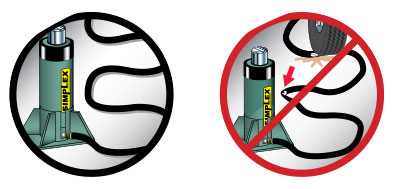
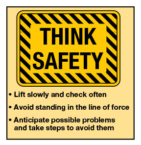
Simplex Hydraulics Safety Tips
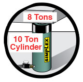
1. Choose The Right Ram.
You must know the weight of what you intend to lift and choose a ram with at least 20% more capacity. Be aware of possible load shift requiring more capacity at any particular lifting point.
2. Inspect All System Components.
Check each component before you set up your hydraulic system. Do not use damaged or worn components. Turn them in for repair or replacement.

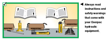
3. Safety Instructions.
Read all warning labels and instructions. Operating instructions must be understood before using equipment. Never remove labels from equipment. Replace missing, worn, or damaged labels. Always wear safety goggles and protective clothing when using hydraulic equipment.

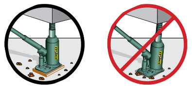
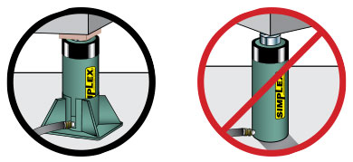
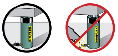
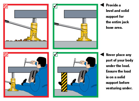
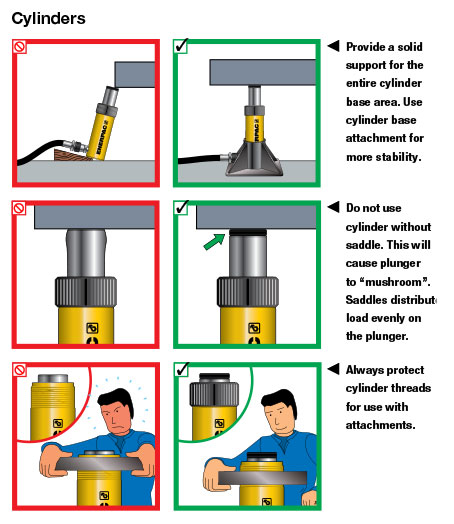
4. Each Jack Or Ram Must Be Fully Supported At The Base.
Every jack or ram, whether used individually or in a system, should be completely supported on a solid, firm, non-sliding foundation capable of supporting the load.
5. Fill Oil Reservoirs With Cylinder Retracted.
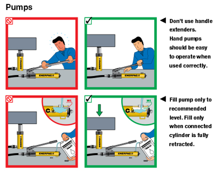
Only fill pump to recommended level, and fill only when connected cylinder is fully retracted.
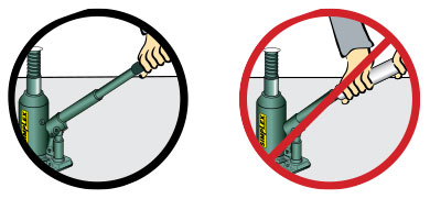
6. Know How Your Hydraulics Work.
Do not use extensions or cheater bars on hydraulic jacks or hand pumps to raise a load.
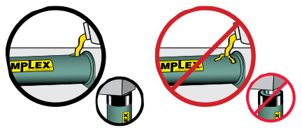
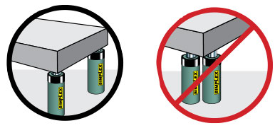
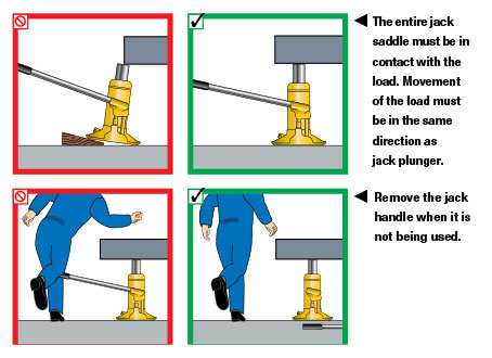
7. Center The Load On The Lifting Point.
The load must be centered on the ram, or equally distributed on multiple rams. Off center loading can result in the ram slipping out and loss of the load.
8. When Using Multiple Rams, Distribute The Load Evenly.
For multiple ram lifts, you must be able to determine the location and number of lifting points that will allow the load to be evenly distributed to all the rams. Size, center of gravity, and load geometry must be considered in order to correctly determine load balance.
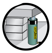
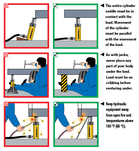
9. Block Or Crib Your Load As It Raises.
Place blocking or cribbing under the loads as you raise it. Each time you raise it higher, insert more blocking. Position yourself in a manner that will keep you clear of the load, and will not allow your hands or other body parts between the load and the cribbing.
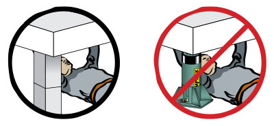
10. Do Not Use Rams As Permanent Supports.
Hydraulic rams are not meant to be used as permanent supports, but are designed to lift and lower. If you need to hold the load for any length of time, cribbing or Simplex locknut cylinders should be used.
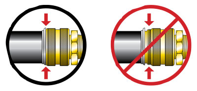
11. Hydraulic Connections.
When making connections with quick couplers, make sure the couplings are fully engaged. Threaded connections such as fittings, gauges, etc. must be securely tightened and leak free. Never use excessive tightening force that may distort the fittings or strip the thread profile.
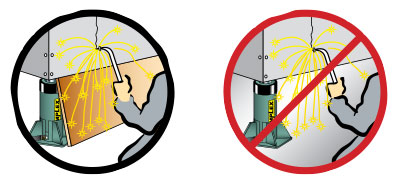
12. Avoid Extreme Heat Or Weld Splatter.
Weld splatter will damage plunger rods and hoses. Hydraulic fluid can ignite if vaporized or exposed to high temperatures.
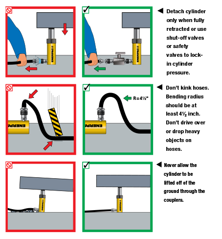
13. Hydraulic Disconnections.
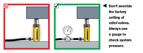
Never attempt to disconnect hydraulic hoses, fittings or couplers under pressure. Unload the ram, open the release screw on the hand pump and shift or open all hydraulic controls several times. If system includes a gauge, double check the gauge to insure pressure has been completely released.
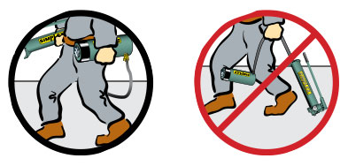
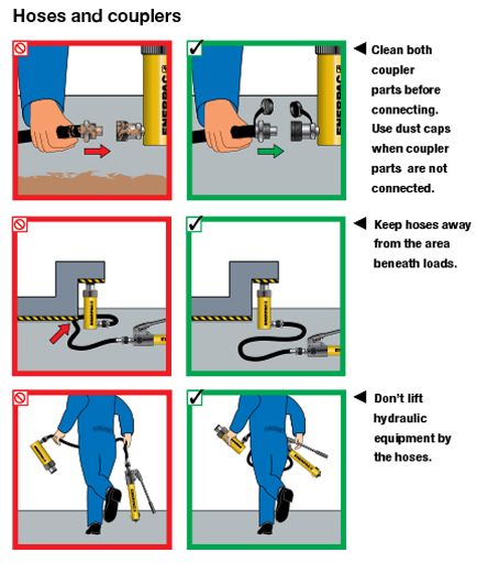
14. Do Not Carry Or Drag Pumps And Rams By Their Hoses.
Dragging or carrying rams or pumps by a connected hose can damage the couplers and hoses. Using damaged couplers and hoses can be dangerous.
15. Keep Hydraulic Hoses Free Of Obstructions.
Do not drop sharp or heavy objects on hose. Keep hose out of heavy traffic areas. This will cause internal damage to hose wire strands. Applying pressure to a damaged hose may cause it to rupture. Avoid sharp bends and kinks when routing hydraulic hoses.
For complete safety information, see TK Simplex at www.tksimplex.com.

Enerpac Hydraulics Safety Instructions
General: Manufacturer’s rating of load and stroke are maximum safe limits. Good practice encourages using only 80% of these ratings!
When used correctly, hydraulic power is one of the safest methods of applying force to your work. To that end we offer some DO’s and DON’Ts, simple common sense points which apply to practically all Enerpac hydraulic products.
The illustrations and application photos of Enerpac products throughout this catalog are used to portray how some of our customers have used hydraulics in industry. In designing similar systems, care must be taken to select the proper components that provide safe operation and fit your needs. Check to see if all safety measures have been taken to avoid the risk of injury and property damage from your application or system. Enerpac cannot be held responsible for damage or injury caused by unsafe use, maintenance or application of its products. Please contact the Enerpac office or a representative for guidance when you are in doubt as to the proper safety precautions to be taken in designing and setting up your particular system.
In addition to these tips, every Enerpac product comes with specific safety information and instructions. Please read them carefully.
For complete safety information, see Enerpac at www.enerpac.com.