Description
General Information—Wire Rope Slings Every Lift Uses 1 of 3 Basic Hitches
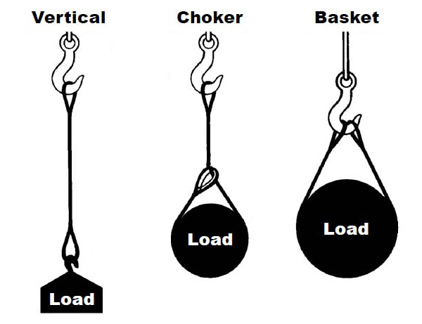
VERTICAL, or straight, attachment is simply using a sling to connect a lifting hook to a load. Full rated lifting capacity of the sling may be utilized, but must not be exceeded. A tagline should be used to prevent load rotation, which may damage a sling.
When two or more slings are attached to the same lifting hook, the total hitch becomes, in effect, a lifting bridle, and the load is distributed equally among the individual slings.
CHOKER hitches reduce lifting capability of a sling since this method of rigging affects ability of the wire rope components to adjust during the lift. A choker is used when the load will not be seriously damaged by the sling body — or the sling damaged by the load, and when the lift requires the sling to snug up against the load.
The diameter of the bend where the sling contacts the load should keep the point of choke against the sling BODY — never against a splice or the base of the eye. When a choke is used at an angle of less than 120 degrees (see next page), the sling-rated capacity must be adjusted downward.
A choker hitch should be pulled tight before a lift is made — NOT PULLED DOWN DURING THE LIFT. It is also dangerous to use only one choker hitch to lift a load which might shift or slide out of the choke.
BASKET hitches distribute a load equally between the two legs of a sling … within limitations described above.
Calculating the Load on Each Leg of a Sling
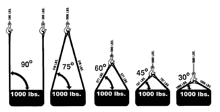
As the included angle between the legs of a sling decreases, the load on each leg increases. The effect is the same whether a single sling is used as a basket or two slings are used with each in a straight pull, as with a 2-legged bridle.
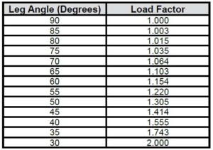
Anytime pull is exerted at an angle on a leg—or legs—of a sling, the load per leg can be determined by using the data in the table above. Proceed as follows to calculate this load—and determine the rated capacity required of the sling, or slings, needed for a lift.
- First, divide the total load to be lifted by the number of legs to be used. This provides the load per leg if the lift were being made with all legs being vertically.
- Determine the angle between the legs of the sling and the horizontal.
- Then MULTIPLY the load per leg (as computed above) by the Load Factor for the leg angle being used (from the table at the bottom) – to compute the ACTUAL LOAD on each leg for this lift and angle. THE ACTUAL LOAD MUST NOT EXCEED THE RATED SLING CAPACITY.
Thus, in the above drawing (sling angle at 60°): 1000 ÷ 2 = 500 (Load Per Leg if a vertical lift) 500 x 1.154 = 577 lbs. – ACTUAL LOAD on each leg at the 60° included angle being used.
In the above drawing (sling angle of 45°): 1000 ÷ 2 = 500 (Load Per Leg if a vertical lift) 500 x 1.414 = 707 lbs. = ACTUAL LOAD on each leg at the 45° horizontal angle being used.
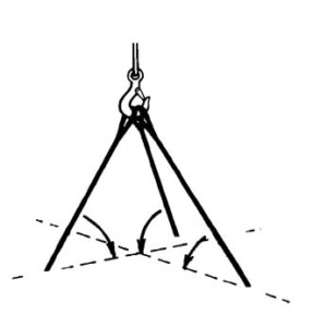
Angles of Bridles
The horizontal angle of bridles with 3 or more legs is measured the same as the horizontal sling angle of 2-legged hitches. In this case, where a bridle designed with different leg lengths results in horizontal angles, the leg with the smallest horizontal angle will carry the greatest load. Therefore, the smallest horizontal angle is used in calculating actual leg load and evaluating the rated capacity of the sling proposed.
Sling Eye Design
Sling eyes are designed to provide what amount to “small inverted slings” at the ends of the sling body. Therefore, the width of the eye opening will be affected by the same general forces which apply to legs of a sling rigged as a basket.
A sling eye should never be used over a hook or pin with a body diameter larger than the natural width of the eye. Never force an eye onto a hook.
On the other hand, the eye should always be used on a hook or pin with at least the nominal diameter of the rope—since applying the D/d Ratio shows an efficiency loss of approximately 50% when the relationship is less than 1/1.
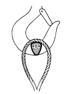
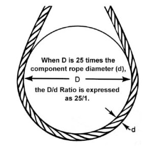
D/d Ratios Apply to Slings
When rigged as a basket, DIAMETER of the bend where a sling contacts the load can be a limiting factor on sling capacity. Standard D/d ratios— where “D” is the diameter of bend, and “d” the diameter of the rope—are applied to determine efficiency of various sling constructions, as indicated below:
- Mechanically Spliced, Single-Part Slings: 25 times rope diameter
- Hand Spliced, Single-Part Slings: 15 times rope diameter.
- Braided Multi-Part Slings of 6 Parts: 25 times component rope diameter.
- Braided Multi-Part Slings of 8 Parts: 25 times component rope diameter.
- Helically Laid Multi-Part Slings: 25 times component rope diameter.
- Cable Laid Slings: 10 times sling body diameter.
- Hand Tucked Grommets & Mechanically Joined Grommets: 5 times sling body diameter.
- Mazzella 7-PartTM Wire Rope Sling: 10 times component rope diameter.
Sling Usage Dictates Sling Body Construction
Whether to use a single-part sling (one made of a single wire rope in the sling body) or a multi-part sling (several ropes in the body) is usually the first decision to make after determining the sling length and capacity for a lift.
The starting point for this decision involves the handling characteristics of the sling more than any other factor. Based on capacity alone, multi-part slings will be more flexible…more easily handled…than single-part slings. The larger the capacity of a sling, the more important this becomes…to the point, it becomes unrealistic to build big capacity slings from single, very large wire ropes.
Multi-part slings provide the only practical means for obtaining extremely heavy lift capacity … in hundreds of tons.
Various approaches to building multi-part slings have been developed; the most common of these are Braided or Multi-Part. These are described in detail elsewhere in this catalog.
Braided, or multi-part, slings are often selected because this construction provides a gripping effect, which reduces load slippage and rotation.
In the design of the sling, rope engineers must seek a balance between strength-handling characteristics and number of parts…since there is a tendency to lose strength as core parts are added to increase flexibility.
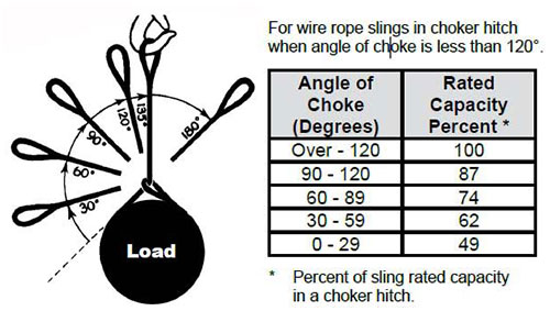
Choker Hitch Rated Capacity Adjustment
If a load is hanging free, the normal choke angle is approximately 135 degrees. When the angle is less than 135 degrees, an adjustment in the sling-rated capacity must be made. Choker hitches at angles greater than 135 degrees are not recommended since they are unstable.
Extreme care should be taken to determine the angle of choke as accurately as possible. In controlled tests, where the angle was less than 120 degrees, the sling body always failed at the point of choke when pulled to destruction. Allowance for this phenomenon must be made anytime a choker hitch is used to shift, turn or control a load, or when the pull is against the choke in a multi-leg lift.
Minimum Sling Body Length
This is the length of wire rope between splices, sleeves or fittings. Generally, the minimum body length is equal to ten (10) times the sling body diameter. This allows approximately one and one half (1-1/2) rope lays between splices. For Multi-part slings, the minimum body length between splices is equal to forty (40) times the component rope diameter.