Instructions and Warnings on the Use Of Steel Wire Rope
The following instructions and warnings combine to provide guidance on product safety and are intended for use by those already having a working knowledge of wire ropes, as well as the new user. They should be read, followed and passed on to others.
The following instructions and warnings combine to provide guidance on product safety and are intended for use by those already having a working knowledge of wire ropes, as well as the new user. They should be read, followed and passed on to others.
Failure to read, understand and follow these instructions could result in harmful and damaging consequences.
1. Rope Selection Criteria
Ensure that the correct type of wire rope is selected for the equipment by referring to the OEM’s instruction manual or other relevant documents. If in doubt, contact Bridon for guidance.
1.1 Rope Strength
If necessary, refer to the appropriate Regulations and/or application standards and calculate the maximum force to which the rope will be subjected.
The calculation may take into account the mass to be lifted or moved, any shock loading, effects of high speed, acceleration, any sudden starts or stops, frequency of operation and sheave bearing friction.
By applying the relevant design factor and, where applicable, the efficiency of the rope termination, the required minimum breaking load or force of the rope will be determined, the values of which are available from the relevant National or International standards or from specific Product Data literature. If in doubt, ask for advice from Bridon.
1.2 Bending Fatigue
The size and number of sheaves in the system will influence the performance of the rope.
Wire rope which bends around sheaves, rollers or drums will deteriorate through ‘bending fatigue’. Reverse bending and high speed will accelerate theprocess. Therefore, under such conditions select a rope with high bending fatigue resistance. Refer to Product Data Information, and if in doubt, ask for advice.
1.3 Abrasion
Wire rope which is subject to abrasion will become progressively weaker as a result of:
Externally—dragging it through overburden, sand or other abrasive materials and passing around a sheave, roller or drum.
Internally—being loaded or bent.
Abrasion weakens the rope by removing metal from both the inner and outer wires. Therefore, a rope with large outer wires should normally be selected.
1.4 Vibration
Vibration in wire rope will cause deterioration. This may become apparent in the form of wire fractures where the vibration is absorbed.
These fractures may be internal only and will not be visually identified.
1.5 Distortion
Wire rope can be distorted due to high pressure against a sheave, improperly sized grooves or as a result of multi-layer spooling on a drum.
Rope with a steel core is more resistant to crushing and distortion.
1.6 Corrosion
Rope with a large number of small wires is more susceptible to corrosion than rope with a small number of large wires. Therefore, if corrosion is expected to have a significant effect on rope performance. The rope may have to be lubricated frequently in service or a galvanized rope may be selected.
1.7 Cabling
‘Cabling’ of rope reeving due to block rotation can occur if the rope is incorrectly selected. Applications involving high lifts are particularly vulnerable to this condition, therefore, ropes specifically designed to resist rotation need to be selected.
1.8 Fixing of Rope Ends
Ropes which have high rotation characteristics must not be selected unless both ends of the rope are fixed or the load is guided and unable to rotate.
1.9 Connecting
Ropes In the event that it is necessary to connect one rope to another (in series), it is essential that they have the required strength, are of the same type and both have the same lay direction (i.e. connect ‘right’ lay to ‘right’ lay).
Failure to heed this warning could result in catastrophic failure particularly at a termination, which is capable of being pulled apart (i.e. splice) due to unlaying.
1.10 Rope Length
Rope length and/or difference in length between two or more ropes used in a set may be a critical factor and must be considered along with rope selection.
Wire rope will elongate under load. Other factors, such as temperature, rope rotation and internal wear, will also have an effect. These factors should also be considered during rope selection.
1.11 Preformed & Non-Preformed Ropes
Single layer round strand rope is normally supplied preformed. However, if a non-preformed rope is selected then personnel responsible for its installation and/or maintenance need to take particular care when handling such rope, especially when cutting.
For the purposes of this instruction, Rotation Resistant ropes should be regarded as non-preformed ropes.
1.12 Operating Temperatures
Wire rope with a steel core should be selected if there is any evidence to suggest that a fiber core will not provide adequate support to the outer strands and/or if the temperature of the working environment may be expected to exceed 180°F.
For operating temperatures above 200°F, de-rating of the minimum breaking force of the rope is necessary (e.g. between 200°F and 400°F reduce by 10%; between 400°F and 600°F reduce by 25%; between 600°F and 800°F reduce by 35%).
Do not use ropes with high carbon wires above 800°F.
Failure to observe this general guidance could result in failure of the ropes to support the load.
For temperatures over 800°F, other materials, such as stainless steel or other special alloys, should be considered.
Rope lubricants and any synthetic filling and/or covering materials may become ineffective at certain low or high operating temperature levels.
Certain types of rope end terminations also have limiting operating temperatures and the manufacturer or Bridon should be consulted where there is any doubt. Ropes with aluminum ferrules must not be used at temperatures in excess of 300°F.
2. Storage
2.1
Unwrap the rope and examine the rope immediately after delivery to check its identification and condition and verify that it is in accordancewith the details on the Certificates and/or other relevant documents.
Check the rope diameter and examine any rope terminations to ensure that they are compatible with the equipment or machinery to which they are to be fitted.
2.2
Select a clean, well ventilated, dry, undercover location. Cover with waterproof material if the delivery site conditions preclude inside storage.
Rotate the reel periodically during long periods of storage, particularly in warm environments, to prevent migration of the lubricant from the rope.
Never store wire rope in areas subject to elevated temperatures as this may seriously affect its future performance. In extreme cases, its original as-manufactured strength may be severely reduced rendering it unfit for safe use.
Ensure that the rope does not make any direct contact with the floor and that there is a flow of air under the reel.
Failure to do so may result in the rope becoming contaminated with foreign matter and start the onset of corrosion before the rope is even put to work.
Support the reel on a simple A-frame or cradle located on ground, which is capable of supporting the total mass of rope and reel. Ensure that the rope is stored where it is not likely to be affected by chemical fumes, steam or other corrosive agents.
Failure to do so may seriously affect its condition rendering it unfit for safe use.
2.3
Examine ropes in storage periodically and, when necessary, apply a suitable dressing which is compatible with the manufacturing lubricant. Contact the rope supplier, Bridon or original equipment manufacturer’s (OEM) manual for guidance on types of dressings available, methods of application and equipment for the various types of ropes and applications.
Re-wrap the rope unless it is obvious that this will be detrimental to rope preservation.
Failure to apply the correct dressing may render the original manufacturing lubricant ineffective and rope performance may be significantly affected.
Ensure that the rope is stored and protected in such a manner that it will not be exposed to any accidental damage either during the storage period or when placing the rope in or taking it out of storage.
Failure to carry out or pay attention to any of the above could result in a loss of strength and/or a reduction in performance. In extreme cases, the rope may be unfit for safe use.
3. Certification and Marking
Make sure that the relevant Certificate has been obtained before taking the rope into use for a lifting operation.
Check to verify that the marking on the rope or its package matches the relevant Certificate.
Note: The rating of a component part of a machine or lifting accessory is the responsibility of the designer of the machine or accessory. Any re-rating of a lifting accessory must be approved by a competent person.
Retain the Certificate in a safe place for identification of the rope when carrying out subsequent periodic statutory examinations in service.
4. Handling and Installation
4.1
Handling and installation of the rope should be carried out in accordance with a detailed plan and should be supervised by a competent person.
Incorrectly supervised handling and installation procedures may result in serious injury to persons in the vicinity of the operation, as well as those persons directly involved in the handling and installation.
4.2
Wear suitable protective clothing, such as overalls, industrial gloves, helmet, eye protectors and safety footwear (and respirator, particularly where the emission of fumes due to heat is likely).
Failure to wear suitable protective clothing and equipment may result in skin problems from over exposure to certain types of rope lubricants and dressings; burns from sparks, rope ends, molten lubricants and metals when cutting ropes or preparing sockets for re-use; respiratory or other internal problems from the inhalation of fumes when cutting ropes or preparing sockets for re-use; eye injuries from sparks when cutting ropes; lacerations to the body from wire and rope ends; bruising of the body and damage to limbs due to rope recoil, backlash and any sudden deviation from the line of path of rope.
4.3
Ensure that the correct rope has been supplied by checking to see that the description on the Certificate is in accordance with that specified in the purchaser’s order.
4.4
Check by measurement that the nominal diameter of the new rope conforms to the nominal size stated on the Certificate.
For verification purposes, measure the diameter by using a suitable rope vernier fitted with jaws broad enough to cover not less than two adjacent strands. Take two sets of measurements spaced at least 3′ apart, ensuring that they are taken at the largest cross-sectional dimension of the rope. At each point, take measurements at right angles to each other
The average of these four measurements should be within the tolerances specified in the appropriate Standard or Specification.
For a more general assessment of rope diameter, use a rope calliper.
4.5
Examine the rope visually to ensure that no damage or obvious signs of deterioration have taken place during storage or transportation to the installation site.
4.6
Check the working area around the equipment for any potential hazards which may affect the safe installation of the rope.
4.7
Check the condition of the rope-related equipment in accordance with the OEM’s instructions. Include the following—
Drum
Check the general condition of the drum.
If the drum is grooved, check the radius and pitch and ensure that the grooves will satisfactorily accommodate the size of the new rope.
Check the condition and position of the kicker plates or wear plates, if fitted, to ensure that the new rope will spool correctly on the drum.
Sheaves
Ensure that the grooving is of the correct shape and size for the new rope
Check that all sheaves are free to rotate and in good condition.
Rope Guards
Check that any rope guards are correctly fitted and are in good condition.
Check the condition of any wear plates or rollers which are protecting structural members.
Failure to carry out any of the above could result in unsatisfactory and unsafe rope performance.
Note: Grooves must have clearance for the rope and provide adequate circumferential support to allow for free movement of the strands and facilitate bending. When grooves become worn and the rope is pinched at the sides, strand and wire movement is restricted and the ability of the rope to bend is reduced.
4.8
When a new rope is fitted, a variation in size compared with the old worn rope will be apparent. The new rope may not fit correctly into the previously worn groove profile and unnecessary wear and rope distortion is likely to occur. This may be remedied by machining out the grooves before the new rope is installed. Before carrying out such action, the sheaves or drum should be examined to ensure that there will be sufficient strength remaining in the underlying material to safely support the rope.
The competent person should be familiar with the requirements of the appropriate application / machinery standard.
Note: General guidance to users is given in the Wire Rope Users Manual.
Transfer the wire rope carefully from the storage area to the installation site.
Coils
Place the coil on the ground and roll it out straight ensuring that it does not become contaminated with dust, grit, moisture or any other harmful material.
If the coil is too large to physically handle it may be placed on a ‘swift’ turntable and the outside end of the rope pulled out allowing the coil to rotate.
Never pull a rope away from a stationary coil as this will induce turn into the rope and kinks will form. These will adversely affect rope performance.
Reels
Pass a shaft through the reel and place the reel in a suitable stand, which allows it to rotate and be braked to avoid overrun during installation. Where multi-layer coiling is involved, it may be necessary for the reel to be placed in equipment which has the capability of providing a back tension in the rope as it is being transferred from reel to drum. This is to ensure that the underlying (and subsequent) laps are wound tightly on the drum.
Position the reel and stand such that the fleet angle during installation is limited to 1.5 degrees.
If a loop forms in the rope, ensure that it does not tighten to form a kink.
A kink can severely affect the strength of a six strand rope and can result in distortion of a Rotation Resistant rope leading to its immediate discard.
Ensure that the reel stand is mounted so as not to create a reverse bend during reeving (i.e. for a winch drum with an overlap rope, take the rope off the top of the reel).
4.9
Ensure that any equipment or machinery to be roped is correctly and safely positioned and isolated from normal usage before installation commences. Refer to the OEM’s instruction manual and the relevant ‘Code of Practice’.
4.10
When releasing the outboard end of the rope from a reel or coil, ensure that this is done in a controlled manner. On release of the bindings and servings used for packaging, the rope will want to straighten itself from its previously bent position. Unless controlled, this could be a violent action. Stand clear.
Failure to control could result in injury.
Ensure that the as-manufactured condition of the rope is maintained during installation.
If installing the new rope with the aid of an old one, one method is to fit a wire rope sock (or stocking) to each of the rope ends. Always ensure that the open end of the sock (or stocking) is securely attached to the rope by a serving or alternatively by a clip. Connect the two ends via a length of fiber rope of adequate strength in order to avoid turn being transmitted from the old rope into the new rope. Alternatively, a length of fiber or steel rope of adequate strength may be reeved into the system for use as a pilot / messenger line. Do not use a swivel during the installation of the rope.
4.11
Monitor the rope carefully as it is being pulled into the system and make sure that it is not obstructed by any part of the structure or mechanism which may cause the rope to come free.
Failure to monitor during this operation could result in injury.
This entire operation should be carried out carefully and slowly under the supervision of a competent person.
4.12
Take particular care and note the manufacturer’s instructions when the rope is required to be cut. Apply secure servings on both sides of the cut mark.
Ensure that the length of serving is at least equal to two rope diameters. (Note: Special servings are required for spiral ropes, i.e. spiral strand and locked coil.)
One serving either side of the cut is normally sufficient for preformed ropes. For non-preformed ropes, (i.e. Rotation Resistant ropes) a minimum of two servings each side of the cut will be necessary.
Arrange and position the rope in such a manner that at the completion of the cutting operation the rope ends will remain in position, thus avoiding any backlash or any other undesirable movement.
Cut the rope with a high speed abrasive disc cutter. Other suitable mechanical or hydraulic shearing equipment may be used although not recommended when a rope end is required to be welded or brazed.
When using a disc cutter be aware of the danger from sparks, disc fragmentation and fumes.
Ensure adequate ventilation to avoid any build-up of fumes from the rope and its constituent parts including any fiber core (natural or synthetic) any rope lubricant(s) and any synthetic filling and/or covering material.
Rope produced from carbon steel wires in the form shipped is not considered a health hazard. During subsequent processing (e.g. cutting, welding, grinding, cleaning), dust and fumes may be produced which contain elements which may affect exposed workers.
The products used in the manufacture of steel wire ropes for lubrication and protection present minimal hazard to the user in the form shipped. The user must however, take reasonable care to minimize skin and eye contact and also avoid breathing their vapor and mist.
4.13
Ensure that any fittings, such as clamps or fixtures, are clean and undamaged before securing rope ends.
Make sure that all fittings are secure in accordance with the OEM’s instruction manual or manufacturer’s instructions and take particular note of any specific safety requirements e.g. torque values (and frequency of any re-application of torque).
When terminating a rope end with a wedge socket, ensure that the rope tail cannot withdraw through the socket by securing a clamp to the tail or by following the manufacturer’s instructions. The tail length should be a minimum of 20 rope diameters for all Rotation Resistant wire rope and a minimum of 6 rope diameters for 6 and 8 strand ropes.
Below are two recommended methods of securing the rope tail of a wedge socket termination:
The loop back method uses a rope grip and the loop should be lashed to the live part of rope by a soft wire serving or tape to prevent flexing of the rope in service.
The method of looping back should not be used if there is a possibility of interference of the loop with the mechanism or structure.
Failure to secure in accordance with instructions could lead to loss of the rope and/or injury.
4.14
When coiling a rope on a plain (or smooth) barrel drum, ensure that each lap lies tightly against the preceding lap. The application of tension in the rope greatly assists in the coiling of the rope.
Any looseness or uneven winding will result in excessive wear, crushing and distortion of the rope.
With plain barrel drums, it is difficult to achieve satisfactory multi-layer coiling beyond three layers.
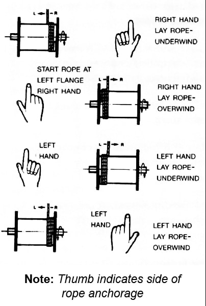
The direction of coiling of the rope on the drum is important, particularly when using plain barrel drums, and should be related to the direction of lay of the rope in order to induce close coiling.
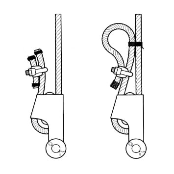
Below is the proper method of locating rope anchorage point on a plain drum:
When multi-layer spooling has to be used it should be realized that after the first layer is wound on a drum, the rope has to cross the underlying rope in order to advance across the drum in the second layer. The points at which the turns in the upper layer cross those of the lower layer are known as the cross-over points and the rope in these areas is susceptible to increased abrasion and crushing. Care should be taken when installing a rope on a drum and when operating a machine to ensure that the rope is spooled and layered correctly.
4.15
Check the state of re-usable rope end terminations for size, strength, defects and cleanliness before use. Nondestructive testing may be required depending on the material and circumstances of use. Ensure that the termination is fitted in accordance with the OEM’s instruction manual or manufacturer’s instructions. When re-using a socket and depending on its type and dimensions, the existing cone should be pressed out. Otherwise, heat may be necessary.
When melting out sockets which have previously been filled with hot metal, the emission of toxic fumes is likely. Note that white metal contains a high proportion of lead.
Correctly locate and secure any connection pins and fittings when assembling end terminations to fixtures.
Refer to manufacturer’s instructions. Failure to pay attention to any of the above could result in unsafe operation and potential injury.
4.16
Limit switches, if fitted, must be checked and readjusted, if necessary, after the rope has been installed.
4.17
Record the following details on the Certificate after installation has been completed: type of equipment, location, plant reference number, duty and date of installation and any re-rating information / signature of competent person. Then safely file the Certificate.
4.18
‘Run in’ the new rope by operating the equipment slowly, preferably with a low load, for several cycles. This permits the new rope to adjust itself gradually to working conditions.
Note: Unless otherwise required by a certifying authority, the rope should be in this condition before any proof test of the equipment or machinery is carried out.
Check that the new rope is spooling correctly on the drum and that no slack or cross laps develop.
Apply as much tension as possible (2%-5% of the MBF of the rope) to ensure tight and even spooling, especially on the first layer.
Where multi-layer spooling is unavoidable, succeeding layers should spool evenly on the preceding layers of rope.
Irregular spooling usually results in severe surface wear and rope malformation, which in turn is likely to cause premature rope failure.
4.19
Ensure that the as-manufactured condition of the rope is maintained throughout the whole of the handling and installation operation.
4.20
If samples are required to be taken from the rope for subsequent testing and/or evaluation, it is essential that the condition of the rope is not disturbed. Refer to the instructions given in 4.12 and, depending on the rope type and construction, any other special manufacturer’s instructions.
5. Inspection
5.1
Inspect the rope and related equipment at the beginning of every work period at least daily in most instances and particularly following any incident which could have damaged the rope or installation.
The entire length of rope should be inspected and particular attention paid to those sections that experience has proven to be the main areas of deterioration. Excessive wear, broken wires, distortion and corrosion are the usual signs of deterioration. For a more detailed examination, special tools are necessary, which will also facilitate internal inspection.
In the case of ropes working over drums or sheaves, it is particularly necessary to examine those areas entering or leaving the grooves when maximum loads (i.e. shock loads) are experienced, or those areas which remain for long periods in exposed places, such as over a jib head sheave.
On some running ropes, but particularly relevant to standing ropes (e.g. pendant ropes), the areas adjacent to terminations should be given special attention by rope diameter measurements and visual examination for broken wires and corrosion.
Note: Shortening the rope repositions the areas of maximum deterioration in the system. Where conditions permit, begin operating with a rope which has a slightly longer length than necessary in order to allow for periodic shortening.
When a non-preformed rope or multi-layer rope is used with a wedge socket and is required to be shortened, it is essential that the end of the rope is secured by welding or brazing before the rope is pulled through the main body of the socket to its new position.
Slacken the wedge in the socket. Pass the rope through the socket by an amount equivalent to the crop length or sample required. Note that the original bent portion of the rope must not be retained within the wedge socket. Replace the wedge and pull up the socket. Prepare and cut in accordance with section 4.12. Ensure that the rope tail cannot withdraw through the socket, see section 4.13.
Failure to observe this instruction will result in a significant deterioration in the performance of the rope and could render the rope completely unfit for further service.
In cases where severe rope wear takes place at one end of a wire rope, the life of the rope may be extended by changing round the drum end with the load end, i.e. turning the rope ‘end for end’ before deterioration becomes excessive.
5.2
Remove broken wires as they occur by bending backwards and forwards using a pair of pliers until they break deep in the valley between two outer strands. Wear protective clothing, such as overalls, industrial gloves, helmet, eye protectors and safety footwear during this operation.
Do not shear off the ends of broken wires with pliers as this will leave an exposed jagged edge, which is likely to damage other wires in the rope and lead to premature removal of the rope from service. Failure to wear adequate protective clothing could result in injury.
Note: Broken wires are a normal feature of service, more so towards the end of the rope’s life, resulting from bending fatigue and wear. The local break up of wires may indicate some mechanical fault in the equipment.
Record the number and position in the rope of any removed broken wires.
5.3
Do not operate an appliance if for any reason (e.g. rope diameter, certified breaking force, rope construction, length or strength and type of rope termination) the wire rope and its termination is considered unsuitable for the required duty.
5.4
Do not operate an appliance if the wire rope fitted has become distorted, been damaged or has deteriorated to a level such that discard criteria has been reached or is likely to be reached prior to normal expected life based on historical performance data.
Rope distortion is usually a result of mechanical damage and can significantly reduce rope strength.
5.5
An authorized competent person must examine the rope in accordance with the appropriate Regulations.
5.6
Do not carry out any inspection, examination, dressing / lubrication, adjustment or any other maintenance of the rope while it is suspending a load, unless otherwise stated in the OEM’s instruction manual or other relevant documents.
Do not carry out any inspection or maintenance of the rope if the appliance controls are unattended unless the surrounding area has been isolated or sufficient warning signs have been posted within the immediate vicinity. If the appliance controls are attended, the authorized person must be able to communicate effectively with the driver or controller of the appliance during the inspection process.
5.7
Never clean the wire rope without recognizing the potential hazards associated with working on a moving rope.
Failure to pay attention or take adequate precaution could result in injury.
If cleaning by cloth / waste, the material can be snagged on damaged surfaces and/or broken wires.
If cleaning by brush, eye protectors must be worn. If using fluids, it should be recognized that some products are highly inflammable. A respirator should be worn if cleaning by a pressurized spray system.
Failure to take adequate precaution could result in injury or damage to health.
Only use compatible cleaning fluids which will not impair the original rope lubricant nor affect the rope associated equipment.
The use of cleaning fluids (particularly solvent based) is likely to ‘cut back’ the existing rope lubricant leading to a greater quantity of lubricant accumulating on the surface of the rope. This may create a hazard in appliances and machinery which rely on friction between the rope and the drive sheave (e.g. elevators, friction winders and ski lifts).
5.8
Lubricants selected for in-service dressing must be compatible with the rope manufacturing lubricant and should be referenced in the OEM’s instruction manual or other documents approved by the owner of the appliance. If in doubt, contact Bridon.
5.9
Take particular care when applying any in-service lubricant / dressing. Application systems which involve pressure should only be operated by trained and authorized persons and the operation carried out strictly in accordance with the manufacturer’s instructions.
Most wire ropes should be lubricated at regular intervals (including cleaning) in order to extend safe performance.
Ensure that any in-service lubricant dressing penetrates into the core of the rope.
Ensure that the in-service lubricant dressing is not applied excessively so that the amount of lubricant on the rope will hinder rope examination.
A ‘dry’ rope unaffected by corrosion, but subject to bend fatigue, is likely to achieve only 30% of that normally attained by a ‘lubricated’ rope.
Note: The authorized person carrying out a rope inspection must be capable of recognizing the potential loss of safe performance of such a rope in comparison with lubricated rope.
Clean the rope before applying a fresh dressing / lubricant if it is heavily loaded with foreign matter e.g. sand, dust.
5.10
The authorized person responsible for carrying out wire rope maintenance must ensure that the ends of the rope are secure. At the drum end, this will involve checking the integrity of the anchorage and ensuring that there are at least three dead wraps tightly spooled.
At the outboard end, the integrity of the termination must be checked to ensure that it is in accordance with the OEM’s manual or other documents approved by the owner of the appliance.
Adjust the lengths of ropes in multi-rope systems in order that equal forces (within approved limits) are evident.
5.11
Damage to, or removal of, component parts (mechanical or structural) caused by abnormal contact with wire rope can be hazardous to the safety of the appliance and/or the performance of the rope (e.g. damage to the drum grooving such that spooling is erratic and/or the rope is ‘pulled down’ into underlying layers, which might cause a dangerous condition or, alternatively, cause localized rope damage at ‘cross-over’ positions, which might then radically affect performance; loss / removal of wear plates protecting the structure leading to major structural damage by cutting and/or failure of the wire rope due to mechanical severance).
5.12
Following any periodic examination or routine or special inspection where any corrective action is taken the Certificate should be updated and a record made of the defects found, the extent of the changes and the condition of the rope.
5.13
Apply the following procedures for the selection and preparation of samples, from new and used lengths of rope, for the purpose of examination and testing to destruction.
Check that the rope end, from which the sample will be taken, is secured by welding or brazing. If not, select the sample length further away from the rope end and prepare new servings.
Handle the rope in accordance with the instructions given in Section 4. Serve the rope using the buried wire technique and apply a rope clamp or grip as close to the cut mark as practically possible. Do not use solder to secure the servings.
Ensure that the sample is kept straight throughout the whole procedure and ensure that the minimum sample length is 10′ unless otherwise specified.
The rope should be cut with a high speed abrasive disc cutter or an oxyacetylene torch. Weld the rope ends of the sample as described in section 4.12, after which the clamp or grip can be removed.
The identification of the rope must be established and the sample suitably marked and packed. It is recommended that the 10′ sample is retained straight and secured to a wood pallet for transportation.
Failure to comply with these procedures will result in measured breaking force values which are not truly representative of the actual strength of the rope.
6. Wire Rope Discard
6.1
Discard the wire rope in accordance with current Regulations and in accordance with the OEM’s instruction manual.
Note: The authorized competent person should also be familiar with the latest versions of ANSI, ASME or ISO Standards. Other standards and instructions covering rope discard may also be applicable. In the case of synthetic sheaves (or synthetic linings), refer to the OEM’s instruction manual or contact the sheave (or lining) manufacturer for specific discard criteria.
6.2
If a wire rope is removed from service at a level of performance substantially different to historically established performance data and without any obvious reason(s), contact Bridon for further guidance.
6.3
Only qualified and experienced personnel, taking the appropriate safety precautions and wearing the appropriate protective clothing, should be responsible for removing the wire rope.
Take particular care when removing ropes with mechanical damage as they may fail abruptly during the change-out procedure.
Take the utmost care when removing ‘exhausted / failed’ ropes from drums and sheaves as they may be grossly distorted, lively and tightly coiled.
Failure to take adequate precautions could result in injury.
6.4
Store discarded rope in a safe and secure location or compound and ensure that it is suitably marked to identify it as rope which has been removed from service and not to be used again.
Discarded rope can be a danger (e.g. protruding broken wires, excessive grease / lubricant and rope mass) to personnel and equipment if not handled correctly and safely during disposal.
6.5
Record the date and reason for discard on the certificate before filing for future reference.
6.6
Pay attention to any regulations affecting the safe disposal of steel wire rope.

This page published with permission from Bridon American.