Wire Rope Technical Information
In this article, we outline important technical topics related to wire rope. This information has been sourced from and approved by Bridon American.
In this article, we outline important technical topics related to wire rope. This information has been sourced from and approved by Bridon American. Use the outline to skip to specific sections:
- Properties of Extension of Steel Wire Ropes
- Phase 1: Initial or Permanent Constructional Extension
- Phase 2: Elastic Extension
- Phase 3: Permanent Extension
- Thermal Expansion and Contraction
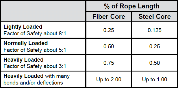
- Pressures Between Ropes and Sheaves or Drums
- Hardness of Rope Wire
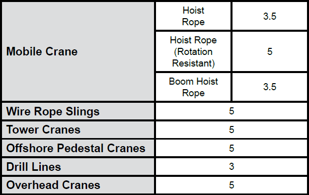
- Design Factor (Minimum Rope Breaking Strength / Maximum Load on Rope)
- Bend Fatigue
- Oversize Tolerance
- Bending Ratios D:d
- The Use of Swivels With Wire Rope
- Group 1
- Group 2
- Group 3a and 3b
- Group 4
- Fleet Angle
- At the Drum
- At the Sheave
- Rope Torque
- Torsional Stability
- Even Number of Falls
- Uneven Number of Falls
- Angular Displacement of Block
- Example
- Cabling Graph
Properties of Extension of Steel Wire Ropes
Any assembly of steel wires spun into a helical formation, either as a strand or wire rope (when subjected to a tensile load) can extend in three separate phases, depending on the magnitude of the applied load.
There are also other factors which produce rope extension, which are very small and can normally be ignored.
Phase 1: Initial or Permanent Constructional Extension
At the commencement of loading a new rope, extension is created by the bedding down of the assembled wires with a corresponding reduction in overall diameter. This reduction in diameter is accommodated by a lengthening of the helical lay. When sufficiently large bearing areas have been generated on adjacent wires to withstand the circumferential compressive loads, this mechanically created extension ceases and the extension in Phase 2 commences. The Initial Extension of any rope cannot be accurately determined by calculation and has no elastic properties.
The practical value of this characteristic depends upon many factors, the most important being the type and construction of rope, the range of loads and the number and frequency of the cycles of operation. It is not possible to quote exact values for the various constructions of rope in use, but the following approximate values may be employed to give reasonably accurate results.
Phase 2: Elastic Extension
Following Phase 1, the rope extends in a manner which complies approximately with Hookes Law (stress is proportional to strain) until the limit of proportionality or elastic limit is reached.
It is important to note that wire ropes do not possess a well defined Young’s Modulus of Elasticity, but an ‘apparent’ Modulus of Elasticity can be determined between two fixed loads.
The Modulus of Elasticity also varies with different rope constructions, but generally increases as the cross-sectional area of steel increases.
By using the values given, it is possible to make a reasonable estimate of elastic extension, but if greater accuracy is required, it is advisable to carry out a modulus test on an actual sample of the rope. As rope users will find it difficult to calculate the actual metallic steel area, the values can be found in the Wire Rope Users Manual or obtained from Bridon Engineering.
Elastic Extension = WL ÷ EA (inches)
W = load applied (pounds)
L = rope length (inches)
E = elastic modulus (pounds/in2)
A = rope area (in2)
Phase 3: Permanent Extension
The permanent, non-elastic extension of the steel caused by tensile loads exceeding the yield point of the material. If the load exceeds the Limit of Proportionality, the rate of extension will accelerate as the load is increased until a loading is reached at which continuous extension will commence, causing the wire rope to fracture without any further increase of load.
Thermal Expansion and Contraction
The coefficient of linear expansion (∝) of steel wire rope is (6.94 x 10⁻⁶ per °F) and therefore the change in length of 1 foot of rope produced by a temperature change of t (°F) would be:
Change in length ΔL = ΔL t where
∝ = coefficient of linear expansion
L = original length of rope (in)
t = temperature change (°F)
The change will be an increase in length if the temperature rises and a decrease in length if the temperature falls.
Extension Due to Rotation
The elongation caused by a free rope end being allowed to rotate.
Extension Due to Wear
The elongation due to inter-wire wear which reduces the cross-sectional area of steel and produces extra constructional extension.
Example: What will be the total elongation of a 200 ft. length of 1-1/8″ diameter Blue Strand 6 x 41 IWRC wire rope at a tension of 20,000 Ibs. and with an increase in temperature of 20°F?
Permanent Constructional Extension = 0.25% of rope length = .5 = 6″
Elastic Extension = WL ÷ EA = 20,000 x 200 x 12 ÷ 13,500,000 x .62 = 5.73″
Thermal Expansion = ΔL = ∝L0 t = 6.94 x 106 x 200 x 20 = .33″
Therefore, Total Extension = 6″ + 5.73″ + .33″ = 12.06″
Pressures Between Ropes and Sheaves or Drums
In addition to bending stresses experienced by wire ropes operating over sheaves or pulleys, ropes are also subjected to radial pressure as they make contact with the sheave. This pressure sets up shearing stresses in the wires, distorts the rope’s structure and affects the rate of wear of the sheave grooves. When a rope passes over a sheave, the load on the sheave bearing results from the tension in the rope and the angle of rope contact. It is independent of the diameter of the sheave.
Load on bearing = 2T sin 0 ÷ 2
T = rope tension (pounds)
0 = angle of rope contact
Assuming that the rope is supported in a well fitting groove, then the pressure between the rope and the groove is dependent upon the rope tension and diameter, but is independent of the arc of contact.
Pressure, P = 2T ÷ Dd
P = pressure (psi)
T = rope tension (pounds)
D = diameter of sheave or drum (in)
d = diameter of rope (in)
It must be realized that this method of estimation of pressure assumes that the area of contact of the rope in the groove is on the full rope diameter, whereas in fact only the crowns of the outer wires are actually in contact with the groove. It is estimated that the local pressures at these contact points may be as high as five times those calculated. If the pressure is high, the compressive strength of the material in the groove may be insufficient to prevent excessive wear and indentation, and this in turn will damage the outer wires of the rope and effect its working life.
As with bending stresses, stresses due to radial pressure increase as the diameter of the sheave decreases. Although high bending stresses generally call for the use of flexible rope constructions having relatively small diameter outer wires, these have less ability to withstand heavy pressures than do the larger wires in the less flexible constructions. If the calculated pressures are too high for the particular material chosen for the sheaves or drums or indentations are being experienced, consideration should be given to an increase in sheave or drum diameter. Such a modification would not only reduce the groove pressure, but would also improve the fatigue life of the rope.
The pressure of the rope against the sheave also causes distortion and flattening of the rope structure. This can be controlled by using sheaves with the correct groove profile, which, for general purposes, suggests a recommended groove diameter of nominal rope diameter +6%. The profile at the bottom of the groove should be circular over an angle of approximately 120° and the angle of flare between the sides of the sheave should be approximately 52°.
Hardness of Rope Wire
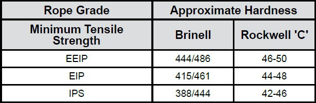
Recommended pulley hardness: 250-300 Brinell for Mn steel or equivalent alloy steel.
Design Factor (Minimum Rope Breaking Strength / Maximum Load on Rope)
Industry standards provide minimum design factors allowed for certain rope applications. Some typical minimum design factors follow:
Bend Fatigue
Bend fatigue testing of ropes usually consists of cycling a length of rope over a sheave while the rope is under a constant tension. As part of their ongoing development program, Bridon has tested literally thousands of ropes in this manner over the years on their own in-house design bend testing equipment.
Through this work, Bridon has been able to compare the effects of rope construction, tensile strength, lay direction, sheave size, groove profile and tensile loading on bend fatigue performance under ideal operating conditions. At the same time it has been possible to compare rope life to discard criteria (e.g. as laid down in ISO 4309) with that to complete failure of the rope, i.e. to the point where the rope has been unable to sustain the load any longer. As part of the exercise, it has also been possible to establish the residual breaking strength of the rope at discard level of deterioration.
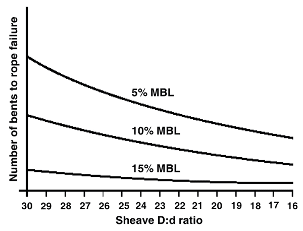
What needs to be recognized, however, is that very few ropes operate under these controlled operating conditions, making it very difficult to use this base information when attempting to predict rope life under other conditions. Other influencing factors, such as dynamic loading, differential loads in the cycle, fleet angle, reeving arrangement, type of spooling on the drum, change in rope direction, sheave alignment, sheave size and groove profile, can have an equally dramatic effect on rope performance.
However, the benefit of such testing can be particularly helpful to the rope manufacturer when developing new or improving existing products.
If designers or operators of equipment are seeking optimum rope performance or regard bending fatigue life as a key factor in the operation of equipment, such information can be provided by Bridon for guidance purposes.

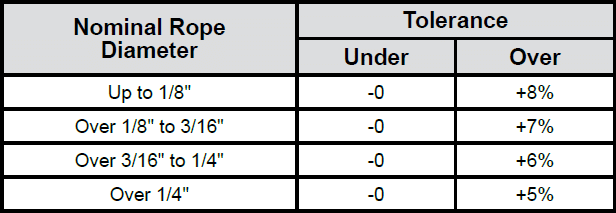
Oversize Tolerance
Wire ropes are manufactured slightly larger than the nominal diameter. The maximum allowable oversize tolerances provided by industry standards are shown in the following table:
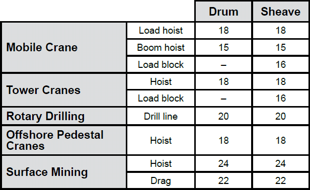
Bending Ratios D:d
Typical minimum bending ratios (sheave or drum dia.: rope dia.) provided by some industry standards are as follows:
The Use of Swivels With Wire Rope
Under certain circumstances it may be necessary to use a swivel in a lifting system to prevent rotation of the load. This is typically done for employee safety considerations. It is possible however, that the use of a swivel will have an adverse affect on rope performance and may, in some cases, damage the wire rope.
There are many types of accessories available that incorporate different types and degrees of rotation- preventing swivels. The swivel may be either an independent accessory or an integral part of a lifting device, such as a crane block with a swivel hook. A typical independent accessory is a ball bearing anti-friction swivel. There are also headache balls with swivel hooks.
The type of swivel that causes the most concern from the standpoint of the wire rope is the independent anti-friction swivel that attaches directly to the rope. The purpose of using a swivel in a lifting system is to prevent rotation of the load. This then allows the wire rope to rotate. Excessive rope rotation can damage a wire rope.
To assist in determining whether or not a swivel should be used in the lifting system, the following recommendations should be considered. It must also be recognized that the rotation characteristics of different types and constructions of wire rope vary considerably. The following types and constructions of wire rope are grouped according to their rotation characteristics.
Group 1
Wire rope constructions having very high rotation characteristics should not be used with a swivel under any circumstances.
These rope constructions will rotate excessively with one end free to rotate, and the rope will unlay and distort and be easily damaged with a loss of rope breaking force.
- Blue Strand 6 x 19 and 6 x 36 Class Lang Lay
- All constructions of Triangular (Flattened) Strand Lang Lay
- Endurance Dyform 8 Lang Lay
- Constructex
Group 2
Wire rope constructions having high rotation characteristics when used in single part reeving may require a swivel in the system to prevent rotation in certain operating conditions. However, this should be done only when employee safety is the issue.
These rope constructions, when used in a reeving system with one end free to rotate, will have a high level of rotation. This will cause the rope to unlay and, to some degree, distortion of the rope will occur.
- Blue Strand 6 x 19 and 6 x 36—Class Regular Lay
- Endurance Dyform 6 and 8 Regular Lay
Group 3a and 3b
The ropes in this Group are designed with an inner rope that is laid in the opposite direction to the outer strands to provide a medium resistance to rotation. Ropes with medium rotation characteristics are used with a swivel in single part reeving applications. However, a swivel is not recommended for multiple part hoisting applications or in any application where the swivel is not necessary for safety reasons. If it is necessary to use a swivel, the rope must be operating at a design factor of 5 or greater, must not be shock loaded and must be inspected daily by a qualified person for distortion.
It should be noted that if a swivel is used on conjunction with Group 3a ropes, rope service life might be reduced due to increased internal wear between the outer strands and the inner rope.
- Group 3a
- Endurance 8RR Rotation Resistant
- Endurance l9 Rotation Resistant
- Group 3b
- Endurance Dyform 18 Rotation Resistant
Group 4
Wire ropes having low rotation characteristics used in either single or multiple part reeving may be used with a swivel. The reason for this is that the ropes will exhibit very little, if any, rotation when used at the proper design factor. Application parameters, such as a fleet angle, may induce turn into a wire rope that can be relieved by the use of a swivel. However, if the application does not induce any turn into the rope, or if a swivel is not beneficial to the performance of the rope, the swivel may not be necessary.
- Endurance 35 LS
- Endurance Dyform 34LR/PI/MAX
Note: When using a swivel with any wire rope, frequent inspection of the rope is necessary. The rope should not be shock loaded or overloaded.
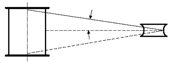
Fleet Angle
Of all the factors which have some influence on the winding of a rope on a smooth drum, the fleet angle, arguably, has the greatest effect.
Fleet angle is usually defined as the included angle between two lines: one which extends from a fixed sheave to the flange of a drum, and the other which extends from the same fixed sheave to the drum in a line perpendicular to the axis of the drum (see illustration).
If the drum incorporates helical grooving, the helix angle of the groove needs to be added or subtracted from the fleet angle as described above to determine the actual fleet angle experienced by the rope.
At the Drum
When spooling rope onto a drum, it is generally recommended that the fleet angle is limited to between 0.5° and 2.5°. If the fleet angle is too small, i.e. less than 0.5°, the rope will tend to pile up at the drum flange and fail to return across the drum. In this situation, the problem may be alleviated by introducing a ‘kicker’ device or by increasing the fleet angle through the introduction of a sheave or spooling mechanism.
If the rope is allowed to pile up, it will eventually roll away from the flange, creating a shock load in both the rope and the structure of the mechanism, an undesirable and unsafe operating condition.
Excessively high fleet angles will return the rope across the drum prematurely, creating gaps between wraps of rope close to the flanges, as well as increasing the pressure on the rope at the cross-over positions.
Even where helical grooving is provided, large fleet angles will inevitably result in localized areas of mechanical damage as the wires ‘pluck’ against each other. This is often referred to as ‘interference’, but the amount can be reduced by selecting a Langs lay rope if the reeving allows. The “interference” effect can also be reduced by employing a Dyform rope, which offers a much smoother exterior surface than conventional rope constructions.
Floating sheaves or specially designed fleet angle compensating devices may also be employed to reduce the fleet angle effect.
At the Sheave
Where a fleet angle exists as the rope enters a sheave, it initially makes contact with the sheave flange. As the rope continues to pass through the sheave it moves down the flange until it sits in the bottom of the groove. In doing so, even when under tension, the rope will actually roll, as well as slide. As a result of the rolling action, the rope is twisted, i.e. turn is induced into or out of the rope, either shortening or lengthening the lay length of the outer layer of strands. As the fleet angle increases, so does the amount of twist.
To reduce the amount of twist to an acceptable level, the fleet angle should be limited to 2.5° for grooved drums and 1.5° for plain drums and when using Rotation Resistant, ropes the fleet angle should be limited to 1.5°.
However, for some crane and hoist applications, it is recognized that for practical reasons. It is not always possible to comply with these general recommendations, in which case, the rope life could be affected.
Rope Torque
The problem of torsional instability in crane hoist ropes would not exist if the ropes could be perfectly torque balanced under load. The torque generated in a wire rope under load is usually directly related to the applied load by a constant ‘torque factor’. For a given rope construction, the torque factor can be expressed as a proportion of the rope diameter and this has been done below.
Variation with rope construction is relatively small and hence the scope for dramatically changing the stability of a hoisting system is limited. Nevertheless, the choice of the correct rope can have a deciding influence, especially in systems which are operating close to the critical limit. It should be noted that the rope torque referred to here is purely that due to tensile loading. No account is taken of the possible residual torque due, for example, to rope manufacture or installation procedures.
Torsional Stability
Torsional Stability and the Cabling Graph are two methods which can be used to determine torsional stability or the tendency of the rope to cable. The torque factors quoted are approximate maximum values for the particular constructions. To calculate the torque value for a particular rope size, multiply by the nominal rope diameter.
Example: for 20mm dia. Dyform 34LR at 20% of minimum breaking force:
| Torque value | = torque factor x rope dia. |
| = 0.76% x 20mm | |
| = 0.152mm |
To calculate the torque generated in a particular rope when subjected to a tensile load, multiply the load by the torque value and combine the units.
Example: for 20mm dia. Dyform 34LR at 6000 kg f load:
| Torque generated | = torque value x load |
| = 0.152 . 6000 | |
| = 912 kgf.mm |
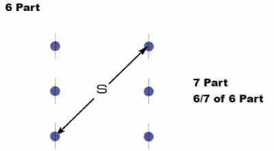
The torsional characteristics of wire rope will have the effect of causing angular displacement of a sheave block when used in multi-fall reeving arrangements. The formula below gives a good approximation under such arrangements.
S2 = 4000L. Tv / sin 0
Where S is the rope spacing in mm
L is the length of each part in the reeving
Tv is the torque value of the rope
0 is the angular displacement of the sheave block
When the angular displacement of the sheave block exceeds 90° (sin 0 = 1) torsional instability results and ‘cabling’ of the reeving will occur. Therefore, the test for stability of any particular reeving can be expressed as:
S>√4000 L. Tv
Where S is the rope spacing in mm
L is length of each part in meters
Tv is torque value in mm
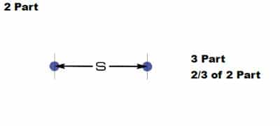
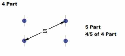
The preceding equations are all relative to a simple two part reeving. For more complex systems, a similar approach may be used if account is taken of the different spacings of the ropes.
Even Number of Falls
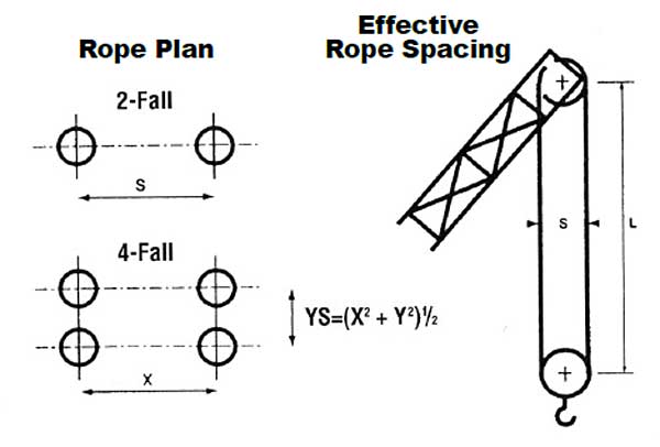
Note: For hoisting arrangements in which the rope falls are not parallel, an average rope spacing should be used.
Uneven Number of Falls
(Rope Termination at Bottom Block)
Effective Rope Spacing and modified formula for stable condition
Effective Rope Spacing S Stable condition if:
S> √6000 . L. / Tv
Angular Displacement of Block
To predict the amount of angular displacement by which a sheave block may turn under the influence of rope torque:
sin0 = (4 000 L. Tv) / S2 (for even number of falls)
The equations assume that rope is torque-free in the noload condition, therefore, induced torque during or immediately after installation will adversely influence the calculated effect.
The above data assumes a constant torque value which is a valid assumption for a new rope. Wear and usage can have a significant effect on the torque value, but practical work shows that under such circumstances, the torque value will diminish, thus improving the stability of the arrangement. Some arrangements may be of such complexity that the evaluation demands a computer study.
Example
Assuming a pedestal crane working on two falls is roped with 20mm diameter DYFORM 34LR and the bottom block carries a sheave of 360mm diameter with the falls parallel:
Torque value = 0.76% x 20 = 0.152mm
If the rope is new (worst condition) and no account is taken of block weight and friction then angular displacement for a height of lift of 30 meters is given by:
sin 0 = (4 000 . 30 . 0.152) / 3602 = 0.141 i.e. 8° 10ꞌ
The reeving would be expected to ‘cable’ at a height of lift calculated as:
| L | = S2 / 4 000 . Tv |
| = 3602 / 4 000 . 0.152 | |
| = 4 000 . 0.152 | |
| = 213 metres |
From the crane designer’s viewpoint, a safety factor against ‘cabling’ should be recognized (angular displacement limited at 30°), hence the practical height of lift is approximately 106.5 meters.
Cabling Graph
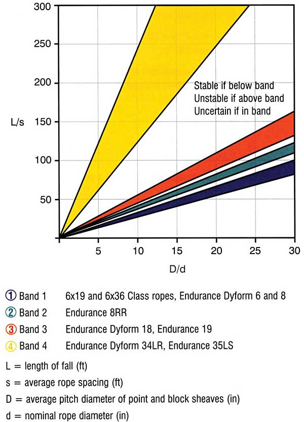
Field research jointly conducted by the Wire Rope Technical Board and the Power Crane and Shovel Association has shown that cabling of the rope parts in a multiple part reeved hoisting arrangement is controlled by several factors. The following calculations and graphs can be used to determine when and if cabling will occur on multiple part reeved hoisting arrangements.
The graph illustrates two dimensional ratios. They are:
- L/S = Length of fall per unit rope spacing
- D/d = Average pitch diameter of traveling and crown block sheave per unit rope diameter.
Various constructions of rope shown on the graph indicate the limited conditions for torsional stability with the angular displacement of the hoist block to a maximum of 90 degrees. When the operating conditions for a particular installation give a resultant above the appropriate band, then cabling of the falls will most likely occur. If the operating conditions give a resultant below any particular band, the cabling of the falls will most likely not occur. If the operating conditions for any particular installation fall within the band, cabling is unpredictable.
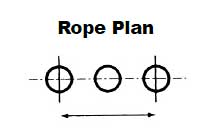
S is determined as follows
S = Spacing (Ft)

This page published with permission from Bridon American.