Inspection of Wire Rope Sheaves and Drums
The very first item to be checked when examining sheaves and drums is the condition of the grooves.
Under normal conditions, machines receive periodic inspections and their overall condition is recorded. Such inspections usually include the drum, sheaves, and any other parts that may come into contact with the wire rope and subject it to wear.
As an additional precaution, rope-related working parts, particularly in the areas described below, should be re-inspected prior to the installation of a new wire rope.
The very first item to be checked when examining sheaves and drums is the condition of the grooves (Figs. 1, 2 and 3). To check the sheave size, contour and amount of wear, a groove gauge is used. As shown in Figure 1, the gauge should contact the groove for about 150° of arc.
Two types of groove gauges are in general use and it is important to note which of these is being used. The two differ by their respective percentage over nominal rope diameter
For new or re-machined grooves, the groove gauge is nominal plus the full oversize percentage. The gauge carried by most wire rope representatives today is used for worn grooves and is made nominal plus 1/2 the oversize percentage.
This latter gauge is intended to act as a sort of “no-go” gauge. Any sheave with a groove smaller than this must be re-grooved or, in all likelihood, the existing rope will be damaged.
When the sheave is re-grooved, it should be machined to the dimensions for “recommended minimum new groove” given. Please refer to the Wire Rope Users Manual or contact your local Lifting Specialist for the table that lists requirements for new or re-machined grooves. The chart gives the groove gauge diameter in terms of the nominal wire rope diameter plus a percentage thereof.
Similarly, the size of the “no-go” gauge is given, against which worn grooves are judged. Experience has clearly demonstrated that the service life of the wire rope will be materially increased by strict adherence to these standards.
Figure 1:
Cross-sections illustrating three sheave groove conditions: A is correct, B is too tight and C is too loose.
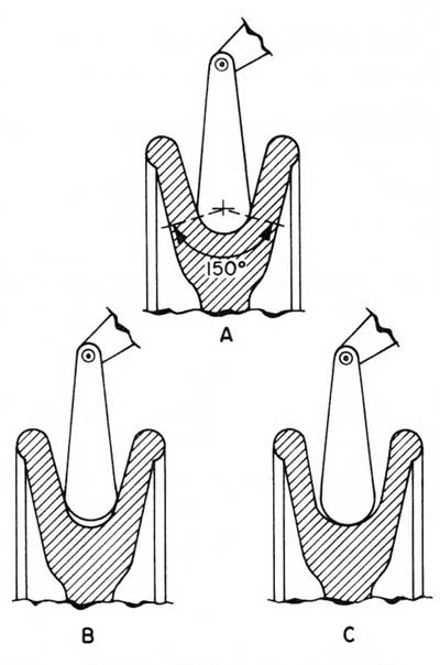
Figure 2:
These sheave groove cross-sections represent three wire rope seating conditions: A is a new rope in a new groove, B is a new rope in a worn groove and C is a worn rope in a worn groove. (See also Figs. 1 and 3)
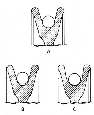
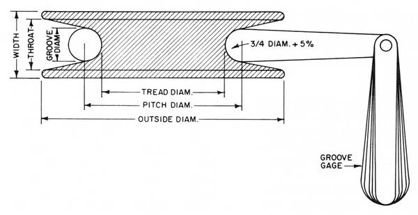
Figure 3:
Illustrating the various dimensions of a sheave and the use of a sheave gauge.