ASME BTH-1: Common Terms Used in Lifting Device Design
“Design is the method of putting form and content together.”
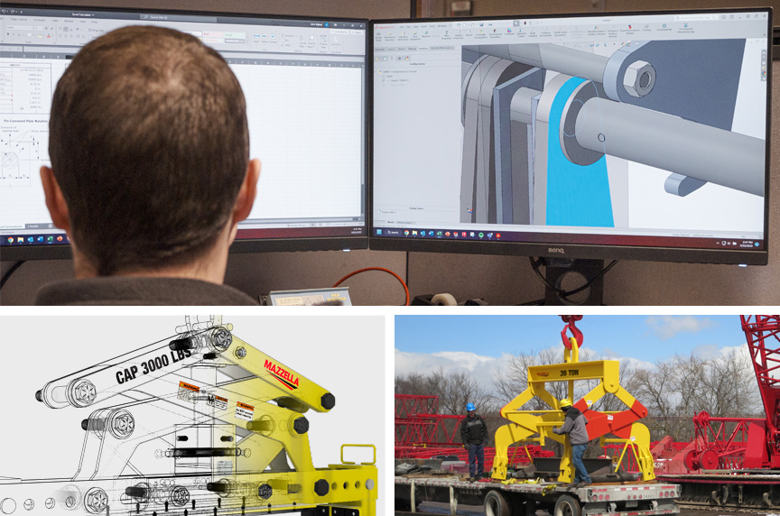
American designer Paul Rand’s words may not have been intended for the lifting and rigging industry, but they translate well. That is especially true when it comes to designing below-the-hook lifting devices, as it is both art and science.
Often, we hear the question: “Why would I waste time and money ordering a custom-engineered below-the-hook lifting device when I have an in-house engineer who could design and create one?”
While in-house engineers may have the mechanical skills and knowledge to make a device, they may not be familiar with the latest design standards, or have access to proof-testing equipment to make sure all design factors are considered.
Designing compliant lifters is so complex that they actually have their own standard, ASME BTH-1 Design of Below-The-Hook Lifting Devices. This standard outlines everything that needs to be done for a below-the-hook lifting device to be compliant.
Educating yourself on the basics of below-the-hook lifting devices is a great way to jumpstart learning, as well as help save time and money when meeting with a third-party manufacturer. The more you know going into design meetings, the easier the process should be.
In this article, you will learn about:
- Basic terms associated with below-the-hook lifting devices
- Definitions for structural design
- Terms for mechanical design
- Definitions for electrical design
- Terms for lifting magnet design
What Is ASME BTH-1?
ASME BTH-1, which was updated in 2020, outlines the following:
“This standard sets forth design criteria for ASME B30.20 Below-the-Hook Lifting Devices. It serves as a guide to designers, manufacturers, purchasers, and users of below-the-hook lifting devices.
Also, this Standard provides minimum structural, mechanical, and electrical design criteria for ASME B30.20 Below-the-Hook Lifting Devices.
The provisions in this Standard apply to the design or modification of below-the-hook lifting devices. Compliance with requirements and criteria that may be unique to specialized industries and environments is outside the scope of this Standard.
Lifting devices designed to this Standard shall comply with ASME B30.20, Below-the-Hook Lifting Devices. ASME B30.20 includes provisions that apply to the marking, construction, installation, inspection, testing, maintenance, and operation of below-the-hook lifting devices.
The provisions defined in this Standard address the most common and broadly applicable aspects of the design of below-the-hook lifting devices. A qualified person shall determine the appropriate methods to be used to address design issues that are not explicitly covered in the Standard so as to provide design factors and/or performance consistent with the intent of this Standard.”

What Are the Basic Terms Associated with Below-the-Hook Lifting Devices?
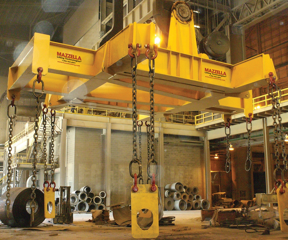
A below-the-hook lifter is a device, other than a load block, used for attaching a load to a hoist.
The device may contain components such as slings, hooks, and rigging hardware that are addressed by ASME B30 volumes or other standards.
Brittle Fracture
Brittle fracture is abrupt cleavage with little or no prior ductile deformation.
Dead Load
This phrase refers to the weights of the parts of the lifting device.
Design
This is the activity in which a qualified person creates devices, machines, structures, or processes to satisfy a human need.
Design Factor
The design factor is the ratio of the limit state stress(es) or strength of an element to the permissible internal stress(es) or forces created by the external force(s) that act upon the element.
Fatigue
Fatigue is the process of progressive localized permanent material damage that may result in cracks or complete fracture after a sufficient number of load cycles.
Fatigue Life
This is the number of load cycles of a specific type and magnitude that a member sustains before failure.
Hoist
A hoist is a machinery unit that is used for lifting and lowering.
Lifting Attachment
The lifting attachment is a load-supporting device, such as a lifting lug, pad eye, trunnion, or similar appurtenance that is attached to the lifted load, is designed for use with the specific load to which it is attached, and either:
- Remains attached to the load
- Is removed and not reused
Limit State
A limit state is a condition in which a structure or component becomes unfit for service, such as brittle fracture, plastic collapse, excessive deformation, durability, fatigue, or instability, and is judged either to be no longer useful for its intended function (serviceability limit state) or to be unsafe (strength limit state).
Load Block
The load block is the assembly of a hook or shackle, swivel, bearing, sheaves, pins, and frame suspended by the hoisting rope or load chain.
Load Cycle
A load cycle refers to one sequence of loading defined by a range between minimum and maximum stress.
Manufacturer
This is the person, company, or agency responsible for the design, fabrication, or performance of a below-the-hook lifting device or lifting device component.
Maximum Stress
Maximum stress is the highest algebraic stress per load cycle.
Mechanical Component
This is the combination of one or more machine elements along with their framework, fastenings, etc., designed, assembled, and arranged to support, modify, or transmit motion, including, but not limited to, the pillow block, screw jack, coupling, clutch, brake, gear reducer, and adjustable-speed transmission.
Minimum Stress
This is the lowest algebraic stress per load cycle.
Modification
This refers to any change, addition to, or reconstruction of a lifter component.
Qualified Person
A qualified person is a person who, by possession of a recognized degree in an applicable field or certificate of professional standing, or who, by extensive knowledge, training, and experience, has successfully shown the ability to solve or resolve problems relating to the subject matter and work.
Rated Load
The rated load is the maximum load for which the lifting device is designated by the manufacturer.
Serviceability Limit State
This is the limiting condition affecting the ability of a structure to preserve its maintainability, durability, or function of machinery under normal usage.
Shall
Shall is a word indicating a requirement.
Should
Should is a word used to indicate a recommendation.
Strength Limit State
This is the limiting condition affecting the safety of the structure, in which the ultimate load-carrying capacity is reached.
Stress Concentration
Stress concentration refers to the localized stress considerably higher than average (even in uniformly loaded cross sections of uniform thickness) due to abrupt changes in geometry or localized loading.
Stress Range
This is the algebraic difference between maximum and minimum stress. Tension stress is considered to have the opposite algebraic sign from compression stress.
Structural Member
This is a component or rigid assembly of components fabricated from structural shape(s), bar(s), plate(s), forging(s), or casting(s).
What Are the Terms Used for Structural Design?
Chapter 3 of the ASME BTH-1 standard outlines design requirements for the structural unit itself. To better understand this section, familiarize yourself with the following terms.
Block Shear
A mode of failure in a bolted or welded connection that is due to a combination of shear and tension acting on orthogonal planes around the minimum net failure path of the connecting elements.
Compact Section
A structural member cross section that can develop a fully plastic stress distribution before the
onset of local buckling.
Effective Length
The equivalent length Kl used in compression formulas.
Effective Length Factor
The ratio between the effective length and the unbraced length of the member measured between the centers of gravity of the bracing members.
Effective Net Tensile Area
The portion of the gross tensile area that is assumed to carry the design tension load at the member’s connections or at locations of holes, cutouts, or other reductions of cross-sectional area.
Effective Width
The reduced width of a plate that, with an assumed uniform stress distribution, produces the same effect on the behavior of a structural member as the actual plate width with its nonuniform stress distribution.
Faying Surface
The plane of contact between two plies of a bolted connection.
Gross Area
A full cross-sectional area of the member.
Local Buckling
The buckling of a compression element may precipitate the failure of the whole member at a stress level below the yield stress of the material.
Noncompact Section
A structural member cross section that can develop the yield stress in compression elements before local buckling occurs, but will not resist inelastic local buckling at strain levels required for a fully plastic stress distribution.
Prismatic Member
A member with a gross cross section that does not vary along its length.
Prying Force
A force due to the lever action that exists in connections in which the line of application of the applied load is eccentric to the axis of the bolt, causing deformation of the fitting and an amplification of the axial force in the bolt.
Slip-Critical
A type of bolted connection in which shear is transmitted by means of the friction produced between the faying surfaces by the clamping action of the bolts.
What Are the Terms Used for Mechanical Design?
Chapter 4 of the ASME BTH-1 standard outlines design requirements for the mechanical parts of the below-the-hook lifting device. To better understand this section, familiarize yourself with the following terms.
Back-Driving
A condition where the load imparts motion to the drive system.
Coefficient of Static Friction
The nondimensional number obtained by dividing the friction force resisting initial motion between two bodies by the normal force pressing the bodies together.
Drive System
An assembly of components that governs the starting, stopping, force, speed, and direction imparted to a moving apparatus.
Equalizing Sheave
A sheave used to equalize tension in opposite parts of a rope. Because of its slight movement, it is not termed a running sheave.
Fluid Power
Energy transmitted and controlled by means of a pressurized fluid, either liquid or gas. The term applies to both hydraulics, which uses a pressurized liquid such as oil or water, and pneumatics, which uses compressed air or other gases.
L10 Bearing Life
The basic rating or specification life of a bearing.
Lock-Up
A condition whereby friction in the drive system prevents back-driving.
Pitch Diameter
The diameter of a sheave measured at the centerline of the rope.
Running Sheave
A sheave that rotates as the load is lifted or lowered.
Sheave
A grooved wheel used with a rope to change direction and point of application of a pulling force.
Vacuum
Pressure less than ambient atmospheric pressure.
Vacuum Lifter
A vacuum lifter is a below-the-hook lifting device for lifting and transporting loads using a holding force by means of vacuum.
Vacuum Pad
A device that applies a holding force on the load by means of vacuum.
What Are the Terms Used for Electrical Design?

Chapter 5 of the ASME BTH-1 standard outlines design requirements for the electrical parts of below-the-hook lifting devices. To better understand this section, familiarize yourself with the following terms.
Brake
A device, other than a motor, used for slowing or stopping motion of an apparatus by friction or power means.
Controller
A device or group of devices that govern, in a predetermined manner, the power delivered to the motor to which it is connected.
Control Panel
An assembly of components that governs the flow of power to or from a motor or other equipment in response to a signal(s) from a control device(s).
Control(s)
A device used to govern or regulate the functions of an apparatus.
Control System
An assembly or group of devices that govern or regulate the operation of an apparatus.
Duty Cycle
Duty cycle is equal to the time on divided by the time on plus time off, and that multiplied by 100. It is expressed as a percentage
Electrical Power Supply
The specifications of the required or supplied electricity such as type (AC or DC), volts, amps, cycles, and phase.
Electric Motor
A rotating machine that transforms electrical energy into mechanical energy.
Externally Powered Electromagnet
A lifting magnet suspended from a crane that requires power from a source external to the crane.
Ground (Grounded)
Electrically connected to earth or to some conducting body that serves in place of the earth.
Master Switch
A manual switch that dominates the operation of contactors, relays, or other remotely operated
devices.
Rectifier
A device for converting alternating current into direct current.
Sensor(s)
A device that responds to a physical stimulus and transmits the resulting signal.
Switch
A device for making, breaking, or changing the connections in an electric circuit.
What Are the Terms Used for Lifting Magnet Design?
Chapter 6 of the ASME BTH-1 standard outlines design requirements for lifting magnet below-the-hook lifting devices. To better understand this section, familiarize yourself with the following terms.
Air Gap
The distance between the surface of the ferrous load and the magnetic pole surfaces of the magnet. This gap may be air space caused by an uneven load surface, rust or scale on the load, paint, oil or coolant, dirt, shop cloths, paper wrapping, etc. The air gap has a permeability, μ0, similar to that of free space.
Coercivity
Demagnetizing force required to reduce the residual magnetic induction of a permanent magnet, Br, to zero.
Effective Magnet Contact Area
The component of a lifting magnet that is in contact with the load. To be considered part of the effective magnet contact area, the area must be part of the magnetic circuit.
Electrically Controlled Permanent Magnet
A lifting magnet that derives holding force from permanent magnet material and requires current only during the period of attachment or release.
Electromagnet Core
The material inside of the power coil designed to absorb the magnetic field and create flux.
Electro-Permanent Magnet Core
The permanent magnet material inside of the power coil. It is designed to retain residual induction after energizing, thereby creating the flux.
Encapsulation Compound
The material that replaces the volume of air inside of the magnetic assembly. Commonly used for vibration reduction, heat dissipation, and insulation to the environmental conditions.
Flux Density (Magnetic Induction)
The magnetic field induced by a magnetic field strength, H, at a given place. The flux density is the flux-per-unit area normal to the magnetic circuit.

Flux Path
The component of a lifting magnet through which the flux must travel to reach the effective magnet contact area.
Flux Source
The component of a lifting magnet that creates the flux. The flux source can be either an electromagnet or a permanent magnet.
Hysteresis Curve
A four-quadrant graph that shows the relationship between the flux density, B, and the magnetic field strength, H, under varying conditions.
Intrinsic Coercive Force
The ability of magnet material to resist demagnetization.
Magnet Duty Cycle
The percentage of time an electromagnet can be energized, Te, relative to total cycle time. De-energized time equals Td. If not rated as continuous, the magnet duty cycle rating includes information on maximum continuous energized time and minimum deenergized time to prevent overheating.
Magnetic Circuit
The magnetic circuit consists of a flux source, a flux path, and the effective magnet contact area. In the “attach” condition, the flux path includes the load. The magnetic circuit in general describes a closed-loop circuit that describes the path from a “north” pole to a “south” pole of the flux source.
Magnetomotive Force
The force that creates flux in a magnetic circuit.
Manually Controlled Permanent Magnet
A lifting magnet that derives holding force from permanent magnet material and requires a manual effort during periods of attachment or release.
Maximum Energy Product
External energy produced by a magnet.
North Pole
The pole exhibiting positive magnetic field characteristics when measured by a magnetic device (opposite of a south pole).
Permanent Magnet Material
A ferromagnetic material that retains a level of residual induction when the external magnetic field strength is reduced to zero.
Permeability
The ratio of the flux density in a material at a point to the magnetic field strength at that point.
Pole
An area of the magnetic circuit that exhibits a constant flux density of either a positive or negative attitude. This can be in either the effective magnet contact area or the flux source.
Power Coil
A solenoid wound around a ferromagnetic electromagnet or electro-permanent magnet core, commonly multiple layers of windings deep. The power coil is used for creating a magnetic field in the core.
Release Mechanism
The component of the lifting magnet that changes the connection to the load between “attach” and “release.”
Reluctance
The ratio between the magnetomotive force acting around a magnetic circuit and the resulting flux.
Residual Magnetic Induction
The intensity of magnetic induction that is retained inside of a magnetic material when the external magnetic field strength is reduced to zero, in a closed magnetic circuit scenario.
South Pole
The pole exhibiting negative magnetic field characteristics when measured by a magnetic device (opposite of a north pole).
How Can Mazzella Help With Your Below-The-Hook Lifting Devices?

As you can see, the processes of designing and building a below-the-hook lifting device are complex. They should be done by trusted professionals who understand the standards and work to adhere to them every day.
Mazzella has more than 65 years of experience in designing and developing custom engineered products, below-the-hook lifting devices, and lifting attachments for use with all types of cranes. On-staff engineers and our commitment to ISO 9001: 2015 guide us to continued success in manufacturing quality products and processes.
Mazzella understands the ASME standards for below-the-hook lifting devices, with an engineer who sits on the ASME B30.20 sub-committee. Also, we have the appropriate insurance coverage to provide you with a device that is certified and backed by the standards. Mazzella lifting devices will meet every OSHA requirement and ASME standard.
We can design and fabricate all types of below-the-hook lifting solutions for any application—all of our work is done in compliance with ASME B30.20 Below-the-Hook Lifting Devices and ASME BTH-1 Design of Below-the-Hook Lifting Devices standards. Our products range from a common lift beam to an engineered special 150-lb. engine line lifter, and 330-ton electric furnace lifter.
Along with design and fabrication, we provide repair or recertification of compliant below-the-hook lifting devices.
Click here if you need a repair or recertification of your lifting device.
Call us at 800.362.4601 or click here to specify your next below-the-hook project!


Below-the-Hook Lifting Devices
We have more than 65 years of experience in designing and developing custom engineered products, below-the-hook lifting devices, and lifting attachments for use with all types of cranes.
On-staff engineering and our commitment to ISO 9001: 2015 guides us to continued success in quality products and processes.